Opto-Isolated Tach/RPM Input Schematic (4N25) - 5V & 12V Mods, Subaru COP Swap
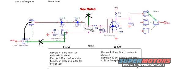
Electronic schematic with opto-isolators, resistors and diodes plus notes for 5V and 12V configurations.
Part of 2012-2016 Subaru Impreza Schematics
This document is an annotated electronic schematic showing an RPM/tachometer input circuit built around a 4N25 opto-isolator (U3). The signal path runs from a TachIn input through a TachSelect jumper and an OptoIn jumper, then through two 1N4001 series diodes (D1 labeled "Wing" and D2 labeled "John"), through resistor R12 to the LED side of the 4N25 opto-isolator. The output side of the opto is pulled up to VCC via a 4.7K resistor (R13), filtered by capacitor C11 (0.01), and routed through OptoOut and Tsel jumpers to an IRQ-1 output. Other jumpers shown include XG1, XG2 (opto-return jumper, Note 4), VrOut, and VrOutInv. Hand-drawn annotations (black lines, green wire, X marks, and a "Removed C30" note) indicate modifications made to the board. A notes table gives two configuration options: for a 5V trigger signal, replace R12 with a 470R resistor, remove C30, and jumper 5V from the proto area to the top hole of C30; for a 12V trigger signal, replace R12 with a 1K resistor, remove C30, and jumper from s12c to the top hole of C30. This appears to be a Megasquirt-style ECU tach input modification guide, filed with a Subaru coil-on-plug conversion document set.
Is this accurate? Sign in to help verify it.
Frequently asked questions
- What opto-isolator is used in this tach input circuit?
- A 4N25 opto-isolator (component U3), labeled 'Opto-isolator' on the schematic.
- How do I configure this circuit for a 5V tach signal?
- Per the notes: remove R12 and fit a 470R resistor in its place, then remove C30 and solder a wire from 5V on the proto area to the top hole of C30.
- How do I configure this circuit for a 12V tach signal?
- Per the notes: remove R12 and fit a 1K resistor in its place, then remove C30 and solder a wire from s12c to the top hole of C30.
- What diodes are in the tach input signal path?
- Two 1N4001 diodes in series, D1 (labeled 'Wing', Note 2) and D2 (labeled 'John', Note 3), between the OptoIn jumper and R12.
- What pull-up resistor is on the opto-isolator output?
- R13, a 4.7K resistor to VCC, with a 0.01 capacitor (C11) on the output line feeding OptoOut and the IRQ-1 signal.
Comments
More from this build



No comments yet.