Home/
Registry/
Ford/
Contour/
1995-2000/
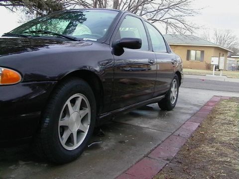
“Nic_ContourSE99”/
Photo
supermotors.net/registry/media/171154
Ford Contour A/C WOT Relay C465 Diagnostic Test A11 - Circuits 15-FA11 & 15-FA12

Service procedure pinpoint test showing step-by-step instructions and meter figures for checking the A/C WOT relay circuit voltage with yes/no branches.
Part of 1995-2000 Ford Contour Service Procedures
This document is a screenshot of a Ford Tech Service (dealerconnection.com) online pinpoint diagnostic procedure page, showing part of an A/C system troubleshooting test involving the A/C WOT (wide open throttle) relay. Step 4 instructs the technician to measure voltage between A/C WOT relay connector C465 pin 3, circuit 15-FA12 (green/blue wire), and ground; if voltage exceeds 10 volts, proceed to test A11, otherwise repair circuit 15-FA12 and retest. Test A11, titled 'CHECK CIRCUIT 15-FA11 (GN/YE) FOR OPEN - PCM CONNECTED', includes a note explaining that if refrigerant pressure is decreasing, the A/C compressor cycling switch opens and no voltage appears at the A/C WOT relay, pressure must be increasing to see voltage there. Step 1 of A11 instructs connecting a test light between A/C WOT relay C465 pin 1, circuit 15-FA11 (green/yellow) and pin 2, circuit 91S-FA11 (black/yellow). If the test light illuminates, go to A14; if not, go to A12. Two illustration figures (VFE0000226 showing a voltmeter connection and VFE0008916 showing test light clips at the relay connector) accompany the steps. A reader learns the exact wire colors, connector pins, and pass/fail voltage criteria for diagnosing the A/C WOT relay circuits.
Is this accurate? Sign in to help verify it.
Frequently asked questions
- What voltage should be present at A/C WOT relay C465 pin 3, circuit 15-FA12?
- The test asks whether the voltage measured between C465 pin 3, circuit 15-FA12 (GN/BU), and ground is greater than 10 volts. If yes, go to test A11; if no, repair circuit 15-FA12 and test for normal operation.
- What wire colors are used for circuits at the A/C WOT relay connector C465?
- Circuit 15-FA12 is GN/BU (green/blue), circuit 15-FA11 is GN/YE (green/yellow) at pin 1, and circuit 91S-FA11 is BK/YE (black/yellow) at pin 2.
- How is test A11 performed on circuit 15-FA11?
- Connect a test light between A/C WOT relay C465 pin 1, circuit 15-FA11 (GN/YE), and pin 2, circuit 91S-FA11 (BK/YE). If the test light illuminates, go to A14; if not, go to A12.
- Why might no voltage appear at the A/C WOT relay during testing?
- The note states that if the pressure is decreasing, the A/C compressor cycling switch will be opened and no voltage will be seen at the A/C WOT relay. The pressure must be increasing to see any voltage at the WOT relay.
Comments
More from this build




No comments yet.