Home/
Registry/
Ford/
Contour/
1995-2000/
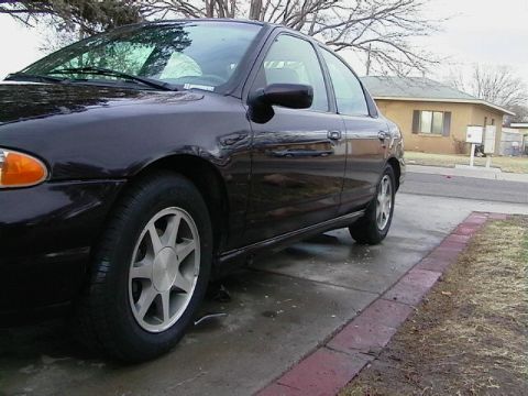
“Nic_ContourSE99”/
Photo
supermotors.net/registry/media/171158
Ford A/C Compressor Clutch Diode Test A18-A19 - Circuits 31-CA6/31-CA7 Diagnosis

Service procedure pinpoint test showing step-by-step instructions and meter figures for checking the A/C compressor clutch diode resistance and continuity.
Part of 1995-2000 Ford Contour Service Procedures
This document is a screenshot of a Ford dealer technical service website (fordtechservice.dealerconnection.com) showing a portion of an A/C system pinpoint diagnostic test procedure. It covers steps in diagnosing the A/C compressor clutch circuit. Step 2 of one test directs measuring resistance between A/C compressor clutch diode connector C972, pin 1, circuit 31-CA7 (BK, black wire) and ground; less than 5 ohms passes to step A18, otherwise circuit 31-CA7 must be repaired. Step A18, 'CHECK THE A/C COMPRESSOR CLUTCH DIODE,' instructs checking continuity between the diode terminals in both directions, continuity in one direction only indicates a good diode (go to A19); otherwise install a new A/C compressor clutch diode. Step A19, 'CHECK CIRCUIT 31-CA6 (BK) FOR OPEN,' begins with measuring resistance between A/C clutch solenoid connector C952, pin 2, circuit 31-CA6 (BK) and ground (the rest of this step is cut off). Illustrations GL1653A and GL1654A show ohmmeter hookups for the measurements. A reader learns the exact connector pins, wire circuit numbers/colors, pass/fail criteria, and repair actions for testing the A/C compressor clutch diode and related ground circuits.
Is this accurate? Sign in to help verify it.
Frequently asked questions
- How do I test the A/C compressor clutch diode?
- Per step A18, check for continuity between the terminals of the A/C compressor clutch diode in both directions. If continuity is indicated in one direction and no continuity in the other, the diode is good (go to A19). If not, install a new A/C compressor clutch diode.
- What resistance should circuit 31-CA7 (BK) show to ground at diode connector C972 pin 1?
- Less than 5 ohms. If resistance is less than 5 ohms, go to step A18; if not, repair circuit 31-CA7 (BK) and test the system for normal operation.
- What does test step A19 check?
- A19 checks circuit 31-CA6 (BK) for an open by measuring resistance between A/C clutch solenoid connector C952, pin 2, circuit 31-CA6 (BK) and ground.
- What should be done if the A/C compressor clutch diode shows continuity in both directions?
- Install a new A/C compressor clutch diode and test the system for normal operation.
Comments
More from this build




No comments yet.