Home/
Registry/
Ford/
F-150/
1980-1986/
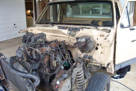
“Blackie for right now”/
Photo
supermotors.net/registry/media/257065
1985 Ford F-150 Auxiliary Reverse Light Switch Wiring Diagram - Relay Trigger

Reference · 1980-1986 F-150All 2 wiring diagrams
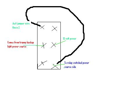
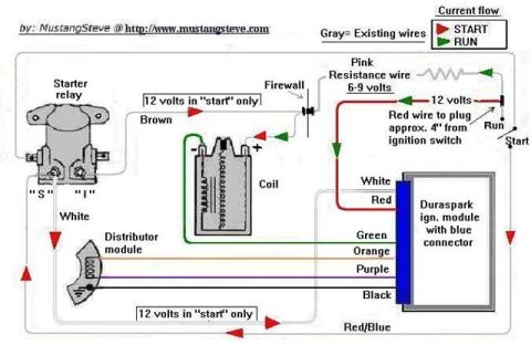

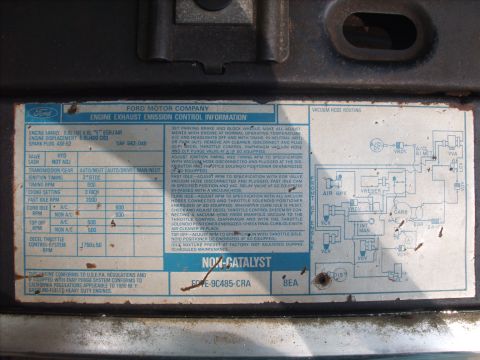
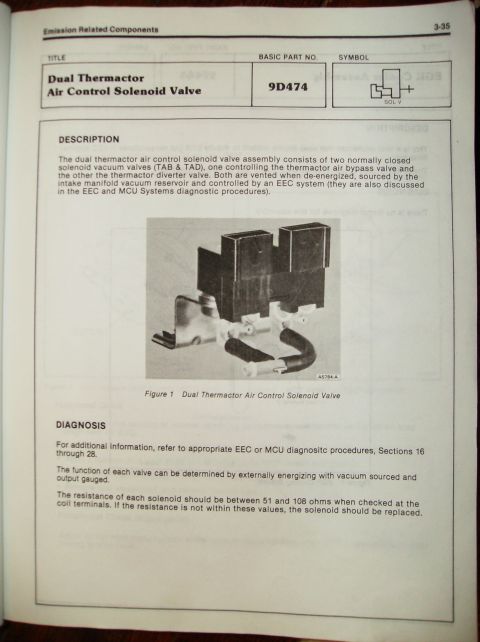
Hand-drawn wiring/connector diagram labeling jumper wires, 12-volt power, transmission backup-light source and relay-switched power terminals.
Part of 1980-1986 Ford F-150 Wiring Diagrams
This is a simple hand-drawn wiring sketch (filename switch.JPG) showing how to wire a six-terminal switch, likely for an auxiliary lighting or relay-triggering setup. The switch is drawn as a rectangle with six terminals marked by X's in three rows of two. The drawing instructs the installer to jumper the two top terminals together, shown by a thick black wire looping from the upper-left terminal around the outside of the switch body to a lower terminal. The middle-left terminal is labeled as receiving power from the transmission backup (reverse) light power source, while the middle-right terminal connects to 12-volt power. A bottom terminal is labeled as the output going to the switched-power source side of a relay. No wire colors, gauge sizes, part numbers, fuse ratings, or vehicle-specific information are given. A reader can learn the basic terminal assignments for wiring this switch so that either the backup-light circuit or a manual 12V feed can trigger a relay, a common setup for adding auxiliary reverse lights that can also be switched on manually. The document does not state a year, make, or model, though it was uploaded to a 1985 Ford F-150 gallery.
Is this accurate? Sign in to help verify it.
Frequently asked questions
- Which switch terminals should be jumpered together?
- The diagram says to jumper the two top terminals of the switch, shown by the thick black wire looping between them.
- Where does the trigger power for this switch come from?
- One middle terminal comes from the transmission backup light power source, and the other middle terminal connects to 12 volt power.
- What does the switch output connect to?
- The output terminal goes to the relay's switched power source side.
- How many terminals does the switch in this diagram have?
- Six terminals, drawn as X marks in three rows of two on the switch body.





No comments yet.