Home/
Registry/
Ford/
Bronco/
1966-1977/
1974 Ford Bronco/
Photo
supermotors.net/registry/media/307956
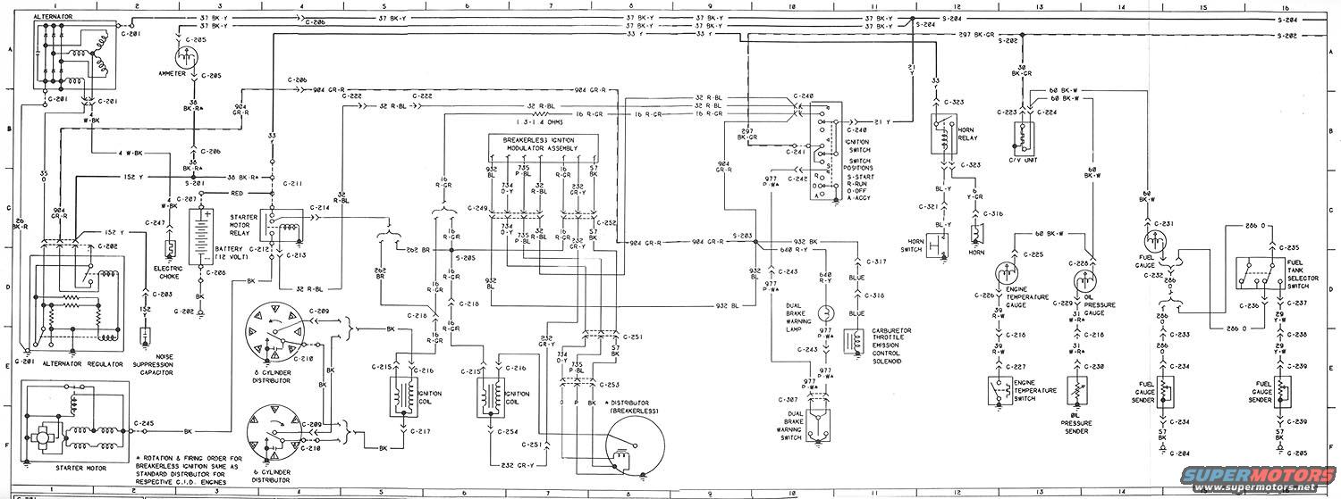
1974 Ford Bronco Wiring Diagram - Ignition, Charging, Gauges & Horn Circuits
Reference · 1966-1977 BroncoAll 10 wiring diagrams
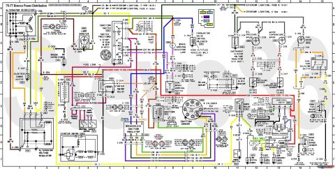


Wiring diagram showing the vehicle electrical system with alternator, ignition, and accessory circuits and coded wires.
Part of 1966-1977 Ford Bronco Wiring Diagrams
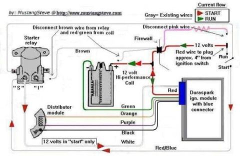
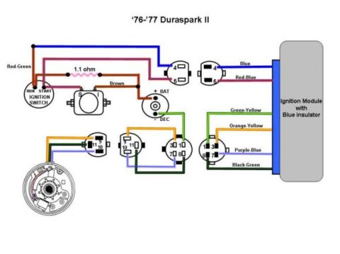
This is a scanned factory-style electrical wiring diagram sheet (grid-referenced A-F rows, columns 1-16) covering the engine compartment and instrument circuits of an early-1970s Ford vehicle, uploaded as a 1974 Ford Bronco reference. It shows the charging system (alternator, alternator regulator, ammeter, noise suppression capacitor), the starting system (starter motor, starter motor relay, 12-volt battery), and both standard and breakerless ignition systems, including 6-cylinder and 8-cylinder distributors, ignition coils, and the breakerless ignition modulator assembly. The ignition switch is shown with its positions labeled S-Start, R-Run, O-Off, and A-Accy. Also included are the horn circuit (horn relay, horn switch, horn), C/V unit, dual brake warning lamp and switch, carburetor throttle emission control solenoid, and gauge circuits: engine temperature gauge/switch, oil pressure gauge/sender, fuel gauge with sender, and a fuel tank selector switch feeding a second fuel gauge sender. Circuit numbers with wire colors are given throughout (e.g., 37 BK-Y, 904 GR-R, 32 R-BL, 16 R-GR, 640 R-Y, 977 P-WA, 286 O), along with connector (C-2xx, C-3xx), ground (G-2xx), and splice (S-2xx) identifiers. A footnote states that rotation and firing order for breakerless ignition is the same as the standard distributor for respective C.I.D. engines.
Is this accurate? Sign in to help verify it.
Frequently asked questions
- What are the ignition switch positions shown on this diagram?
- The ignition switch positions are labeled S-Start, R-Run, O-Off, and A-Accy, shown at connectors C-240 and C-241.
- What wire color feeds the engine temperature gauge circuit?
- The engine temperature gauge circuit uses wire 39 R-W (red-white), running from the gauge at C-226 through C-216 and C-227 to the engine temperature switch.
- Does this diagram cover breakerless ignition?
- Yes. It shows a Breakerless Ignition Modulator Assembly and a breakerless distributor, with a footnote stating rotation and firing order for breakerless ignition is the same as the standard distributor for respective C.I.D. engines.
- What circuit connects the two fuel gauge senders?
- A fuel tank selector switch (C-235/C-236) routes circuit 286 O and 29 Y-W to the fuel gauge senders, which ground through 57 BK wires to G-204 and G-205.
- What wire runs from the alternator across the top of the diagram?
- Circuit 37 BK-Y (black-yellow) runs from the alternator area through C-206 across the top of the diagram to splice S-204.

No comments yet.