Ford F-100 Body Mount Cross-Section Diagram - Punch, Bushing & Bolt Layout
Reference · 1973-1979 F-100All 2 schematics
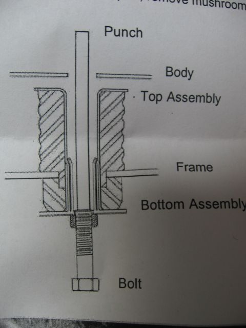
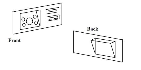

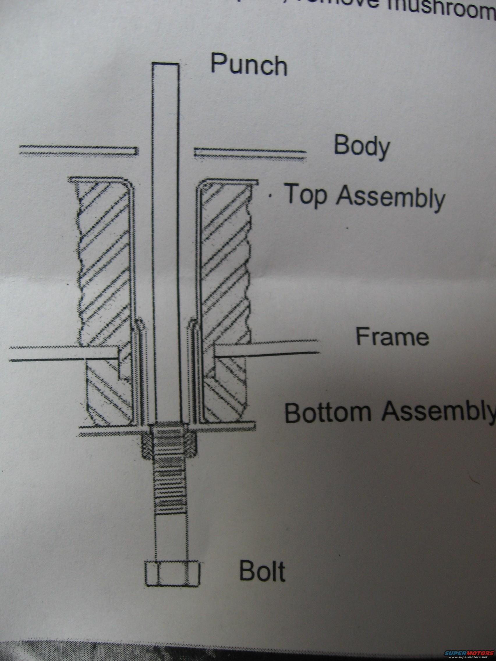
Labeled cross-section schematic of a body mount showing the punch, top and bottom assemblies, frame and bolt.
Part of 1973-1979 Ford F-100 Schematics
This document is a single cross-section schematic illustration, apparently one page from a multi-page instruction set. The diagram shows a vertical punch tool passing down through a vehicle's body panel and frame, illustrating the relationship of a body-to-frame mount stack-up. Callout labels identify six elements from top to bottom: the Punch (a long cylindrical driver inserted from above), the Body (the sheet-metal body panel), the Top Assembly (a hatched rubber/insulator block sitting between the body and frame), the Frame (the horizontal frame rail flange), the Bottom Assembly (a second hatched insulator below the frame), and the Bolt (a long threaded fastener with hex head and nut running up through the assemblies). A fragment of instructional text at the top edge of the scan reads '...remove mushroom...', suggesting the step involves using the punch to drive out or remove a mushroomed component of the body mount. A reader can learn how the body mount components (upper and lower insulator assemblies, through-bolt, and frame) are arranged in cross-section and where a punch is applied during removal or service. No year, make, model, part numbers, dimensions, or torque values appear on this page.
Is this accurate? Sign in to help verify it.
Frequently asked questions
- What components are labeled in this body mount diagram?
- Six items are labeled: Punch, Body, Top Assembly, Frame, Bottom Assembly, and Bolt.
- How are the body mount assemblies arranged relative to the frame?
- The Top Assembly sits between the vehicle Body and the Frame, while the Bottom Assembly sits below the Frame; a long Bolt with a nut passes up through the stack.
- What tool is shown being used in this diagram?
- A punch is shown inserted vertically down through the body and mount assemblies; a text fragment at the top mentions removing a 'mushroom' portion.
- Does this document list torque specs or part numbers?
- No. The visible page contains only the cross-section drawing and its six callout labels, with no torque values, dimensions, or part numbers.
No comments yet.