Home/
Registry/
Pontiac/
Grand Prix/
1997-2003/
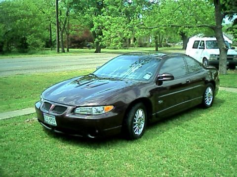
1997 Pontiac Grand Prix/
Photo
supermotors.net/registry/media/548119
GM ABS/ETS Component Location Diagram - 1997 Grand Prix Service Manual 5E2-8
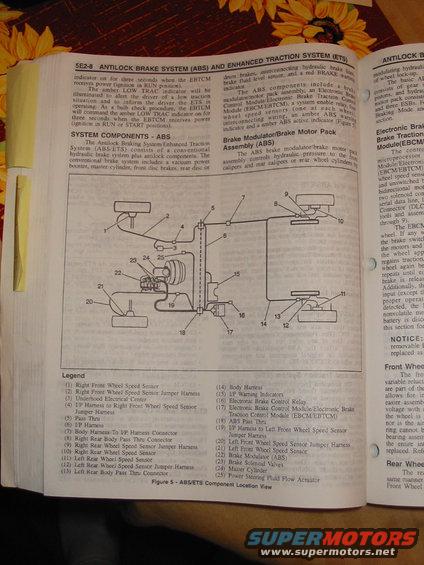
Service manual page for the antilock brake and enhanced traction systems with a component location view and numbered legend.
This is page 5E2-8 from a GM factory service manual section covering the Antilock Brake System (ABS) and Enhanced Traction System (ETS), consistent with the uploader's 1997 Pontiac Grand Prix. The page explains the EBTCM's bulb-check behavior for the ABS and amber LOW TRAC indicators (illuminated for three seconds when the EBTCM receives power in RUN or START), and describes the system components: a conventional hydraulic brake system (vacuum power booster, master cylinder, front disc brakes, rear disc or drum brakes, brake fluid level sensor, red BRAKE warning indicator) plus ABS components including the brake modulator/motor pack assembly, EBCM/EBTCM, system enable relay, four wheel speed sensors, and amber ABS warning/active indicators. The centerpiece is Figure 5, an ABS/ETS Component Location View diagram of the vehicle with 25 numbered callouts, fully itemized in a legend, covering all four wheel speed sensors and their jumper harnesses, pass-thru connectors, the underhood electrical center, I/P and body harnesses, warning indicators, electronic brake control relay, EBCM/EBTCM, brake modulator, brake solenoid valves, master cylinder, and the power steering fluid flow actuator. A reader can use this page to locate every ABS/ETS component and its wiring interconnection points on the vehicle.
Is this accurate? Sign in to help verify it.
Frequently asked questions
- How long does the ABS/LOW TRAC indicator stay on during the bulb check?
- The EBTCM commands the amber LOW TRAC indicator on for three seconds when the EBTCM receives power (ignition in RUN or START positions), and the indicator comes on for three seconds when the EBTCM receives power in the RUN position.
- What components make up the ABS on this vehicle?
- The ABS components include a brake modulator/brake motor pack assembly, an Electronic Brake Control Module/Electronic Brake Traction Control Module (EBCM/EBTCM), a system enable relay, four wheel speed sensors (one at each wheel), interconnecting wiring, an amber ABS warning indicator and an amber ABS active indicator.
- What does the brake modulator/brake motor pack assembly do?
- It controls hydraulic pressure to the front calipers and rear calipers or rear wheel cylinders.
- Where is the EBCM/EBTCM shown in the component location diagram?
- It is callout (17) in Figure 5 - ABS/ETS Component Location View, shown near the brake modulator (22), brake solenoid valves (23), and master cylinder (24) in the engine compartment area of the diagram.
- What does the amber LOW TRAC indicator mean?
- It illuminates to alert the driver of a low traction situation and to inform the driver that the ETS is operating.
Comments
More from this build

No comments yet.