Home/
Registry/
Mercury/
Cougar/
1989-1997/
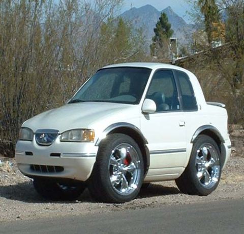
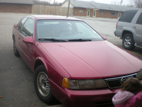
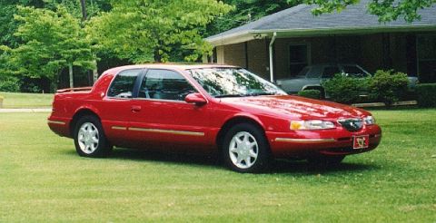
1997 Mercury Cougar/
Photo
supermotors.net/registry/media/621497
C250 Standard Instrument Cluster Connector Pinout - Wire Colors & Functions
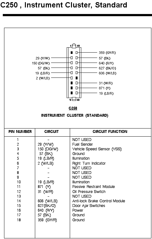
Connector pinout for the C250 standard instrument cluster listing pin numbers, color-coded circuits, and functions.
This document is a connector pinout reference for connector C250, the standard instrument cluster connector. It includes a diagram of the 18-pin connector face showing pin orientation (pins 1/18 at top, 9/10 at bottom) with circuit numbers and wire colors called out for each populated cavity. Below the diagram, a table lists all 18 pins with their circuit numbers, wire colors, and functions. Key circuits include: pin 2, circuit 29 (Y/W) Fuel Sender; pin 3, circuit 150 (DG/W) Vehicle Speed Sensor (VSS); pins 4, 17, and 18, grounds (57 BK, 57 BK, 359 GY/R); pins 5 and 10, circuit 19 (LB/R) Illumination; pin 6, circuit 2 (W/LB) Right Turn Indicator; pin 11, circuit 871 (Y) Passive Restraint Module; pin 12, circuit 31 (W/R) Oil Pressure Switch; pin 14, circuit 606 (W/LB) Anti-lock Brake Control Module; pin 15, circuit 627 (BK/O) Door Ajar Switches; and pin 16, circuit 640 (R/Y) Power. Pins 1, 7, 8, 9, and 13 are not used. This is useful for diagnosing gauge, illumination, VSS, or cluster power/ground issues on vehicles using this standard (non-electronic) cluster.
Is this accurate? Sign in to help verify it.
Frequently asked questions
- What connector is C250?
- C250 is the connector for the standard instrument cluster; it is an 18-pin connector with pins 1 and 18 at the top and 9 and 10 at the bottom.
- Which pin on C250 is the fuel sender?
- Pin 2, circuit 29 with a Yellow/White (Y/W) wire, is the Fuel Sender circuit.
- Where does the Vehicle Speed Sensor (VSS) connect on the standard cluster?
- Pin 3, circuit 150 with a Dark Green/White (DG/W) wire, is the Vehicle Speed Sensor (VSS) input.
- Which pins are power and ground on the C250 standard cluster connector?
- Pin 16 is power (circuit 640, R/Y). Grounds are pin 4 (57 BK), pin 17 (57 BK), and pin 18 (359 GY/R).
- Which pins on C250 are not used?
- Pins 1, 7, 8, 9, and 13 are listed as NOT USED.
Comments
More from this build
No comments yet.