Home/
Registry/
Ford/
Ranchero/
1966-1971/
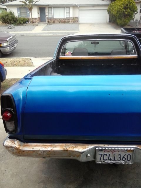
“The RustChero”/
Photo
supermotors.net/registry/media/623435
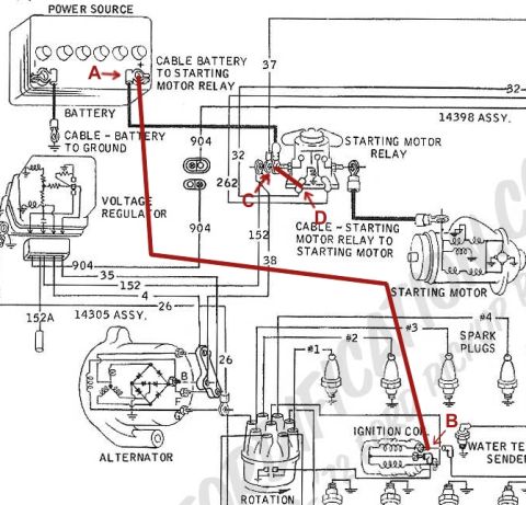
1968 Ford Ranchero Starting & Ignition Wiring Diagram - Hot Wire Bypass Path

Engine electrical wiring diagram showing power source/battery, battery-to-starter-relay cable, starting motor relay/motor, voltage regulator, alternator, distributor, and ignition coil with circuit numbers.
This document is a scanned factory-style Ford engine electrical wiring diagram covering the power source, charging, and starting/ignition circuits. It illustrates the battery (labeled POWER SOURCE), the cable from the battery to the starting motor relay, the battery-to-ground cable, the voltage regulator, the starting motor relay, the cable from the relay to the starting motor, the alternator (with B and F terminals shown), the distributor (marked ROTATION), the ignition coil, four spark plugs (#1-#4), and a water temperature sender. Harness assembly numbers 14398 ASSY. and 14305 ASSY. are called out, along with circuit/wire numbers 37, 32, 262, 904, 152, 152A, 38, 35, 4, and 26. The uploader has added red annotations: callout letters A (battery positive terminal), C and D (starting motor relay terminals), E (relay output to starter cable), and B (ignition coil terminal), plus a bold red line tracing a 'hot wire' path from the battery positive terminal directly to the ignition coil, apparently documenting a hot-wire bypass or diagnostic path. The diagram lets a reader identify starting/charging circuit routing, component locations, terminal identification, and circuit numbers for this Ford engine compartment harness.
Is this accurate? Sign in to help verify it.
Frequently asked questions
- What harness assembly numbers are shown on this diagram?
- The diagram calls out 14398 ASSY. (battery/starter relay cable area) and 14305 ASSY. (alternator/regulator harness area).
- What circuit/wire numbers appear on this wiring diagram?
- Visible circuit numbers include 37, 32, 262, 904, 152, 152A, 38, 35, 4, and 26.
- What does the red line on the diagram indicate?
- A red line traces a path from the battery positive terminal (marked A) down through the diagram to the ignition coil terminal (marked B), with additional red callouts C, D, and E at the starting motor relay, showing a 'hot wire' connection from battery to coil.
- Which components are shown in this diagram?
- The battery (power source), battery-to-starter-relay cable, battery ground cable, voltage regulator, starting motor relay, starting motor, alternator, distributor (rotation), ignition coil, spark plugs #1-#4, and a water temperature sender.
- What cables are labeled on the diagram?
- Three cables are labeled: 'Cable Battery to Starting Motor Relay,' 'Cable - Battery to Ground,' and 'Cable - Starting Motor Relay to Starting Motor.'
Comments
More from this build
No comments yet.