Home/
Registry/
Mercury/
Grand Marquis/
1998-2011/
“98”/
Photo
supermotors.net/registry/media/691571
Mercury Grand Marquis Cornering Light Wiring Diagram - MFS & Relay Mod
Reference · 1998-2011 Grand MarquisAll 5 wiring diagrams


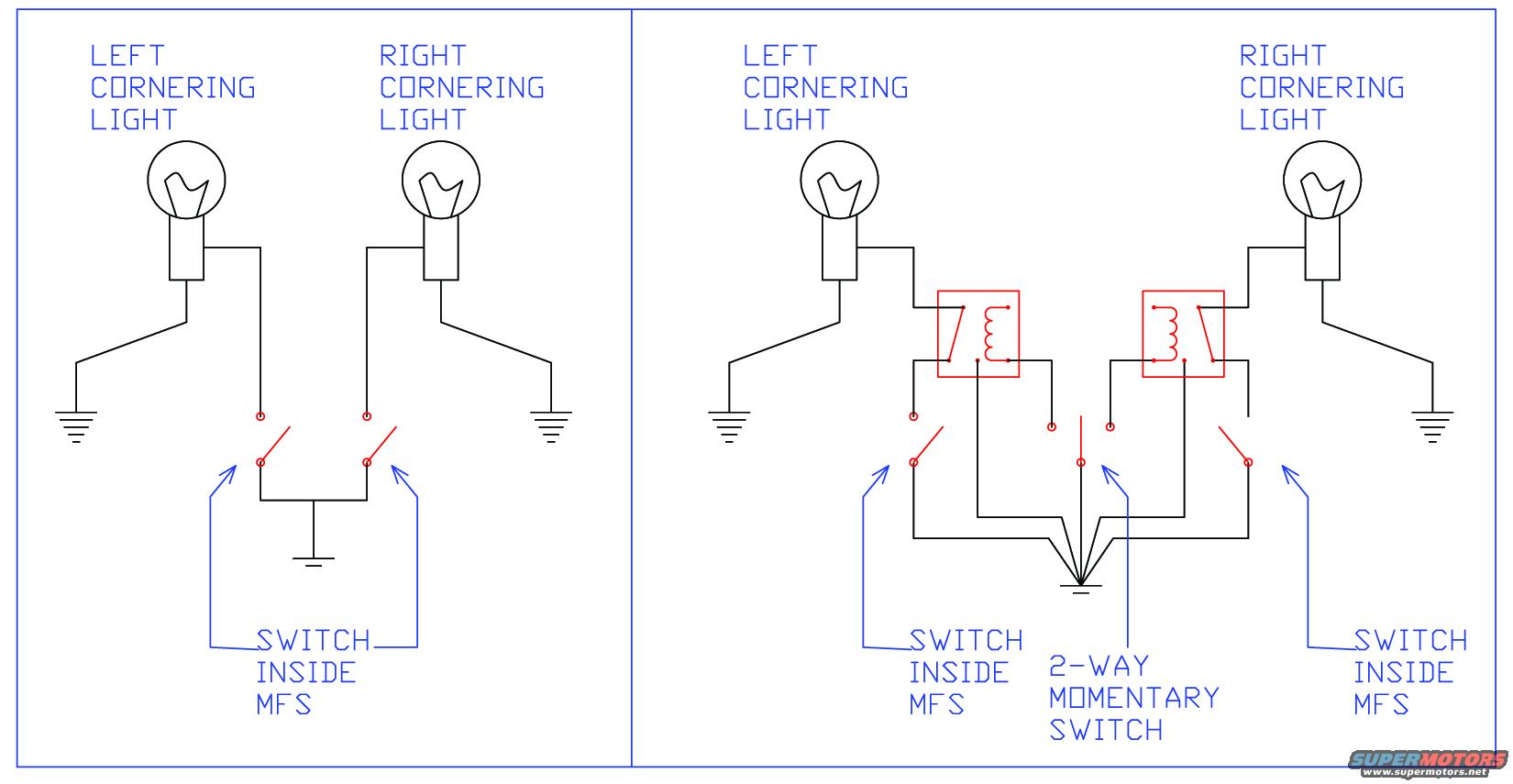
Wiring diagram showing left and right cornering light circuits, the MFS switch, two-way relays, and ground connections.
Part of 1998-2011 Mercury Grand Marquis Wiring Diagrams
This document is a hand-drawn (CAD-style) two-panel wiring schematic showing cornering light circuits, uploaded for a 1998 Mercury Grand Marquis. The left panel shows the stock arrangement: the left and right cornering lights each have one terminal grounded, while the other terminal is switched by contacts inside the MFS (multi-function switch), which share a common ground. The right panel shows a modified circuit: each cornering light is fed through an added relay (drawn in red, with coil and contact shown). Each relay coil can be energized either by the corresponding switch inside the MFS or by an added 2-way momentary switch, all of which return to a common ground point. This allows the cornering lights to be activated manually via the momentary switch in addition to the normal turn-signal (MFS) activation. The diagram contains no wire colors, fuse values, connector pin numbers, or part numbers, it is purely a conceptual schematic. A reader can learn how the factory cornering lights are switched through the multi-function switch and how to add relays plus a two-way momentary switch to independently trigger either cornering light.
Is this accurate? Sign in to help verify it.
Frequently asked questions
- How are the cornering lights switched in the stock circuit?
- Each cornering light has one terminal grounded, and the other terminal is controlled by a switch inside the MFS (multi-function switch); both MFS switch contacts connect to a common ground.
- What does the modified circuit (right panel) add?
- It adds a relay (shown in red) in the feed to each cornering light, plus a 2-way momentary switch, so each light can be triggered either by the switch inside the MFS or by the momentary switch.
- What does the 2-way momentary switch do?
- It provides an alternate path to ground to energize either the left or right relay, allowing manual activation of either cornering light independent of the MFS.
- Does the diagram show wire colors or fuse ratings?
- No. The diagram is a conceptual schematic only; it shows no wire colors, fuse positions, amp ratings, connector pins, or part numbers.



No comments yet.