Home/
Registry/
Ford/
Taurus/
1992-1995/
1993 Ford Taurus/
Photo
supermotors.net/registry/media/726942
Ford Taurus 3.0L/3.0L SHO/3.8L Charging System Wiring Diagram (Alternator IAR)

Reference · 1992-1995 TaurusAll 37 wiring diagrams
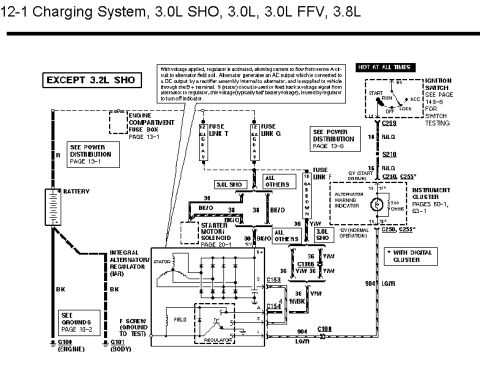
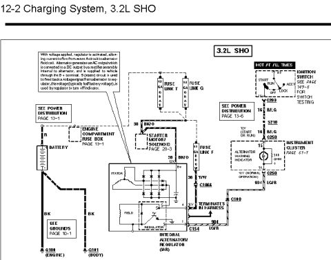
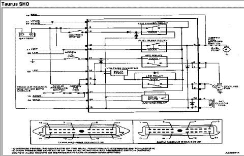
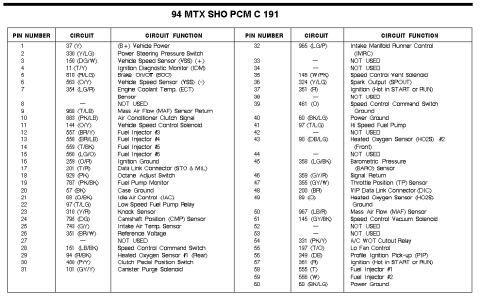
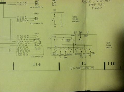
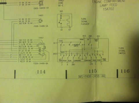
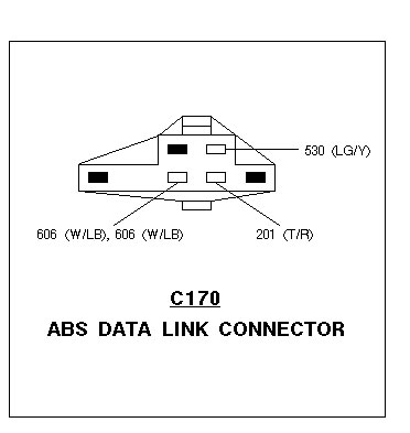
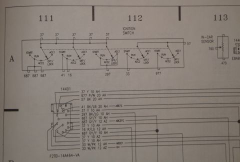
Charging system wiring diagram covering 3.0L SHO, 3.0L, FFV and 3.8L engines with battery, alternator and cluster circuits.
Part of 1992-1995 Ford Taurus Wiring Diagrams
This is page 12-1 of a Ford wiring diagram covering the charging system for 3.0L SHO, 3.0L, 3.0L FFV, and 3.8L engines (labeled 'EXCEPT 3.2L SHO'), consistent with a Ford Taurus service manual. The schematic shows the Integral Alternator/Regulator (IAR) with its stator, field, rectifier, and regulator, and terminals B+, S, A, I, and F (including the F screw ground-to-test point). Power flows from the battery through fuse links T and G (gray) in the engine compartment fuse box (page 13-1), and through fuse link F (16 GA brown) from the ignition switch RUN circuit (16 R/LG via connector C259 and splice S210) to the alternator warning indicator (500 ohms) in the instrument cluster (pages 60-1, 63-1). Wire circuits shown include 36 Y/W, 38/36 BK/O, 36 W/BK, and 904 LG/R, with connectors C153, C154, C1066, C108, C250, and C255 (the latter used with digital cluster). Branching differs between the 3.0L SHO and all other engines at the starter motor/solenoid connection (page 20-1). Grounds G100 (engine) and G101 (body) are referenced to grounds page 10-2. An explanatory note describes regulator operation, AC-to-DC rectification, and how the S (stator) feedback signal turns off the charge indicator.
Is this accurate? Sign in to help verify it.
Frequently asked questions
- Which engines does this charging system diagram cover?
- It covers the 3.0L SHO, 3.0L, 3.0L FFV, and 3.8L engines, and is explicitly labeled 'EXCEPT 3.2L SHO'.
- What type of alternator/regulator is shown?
- An Integral Alternator/Regulator (IAR) with stator, field, rectifier, and regulator, using terminals B+, S, A, and I, plus an F screw that can be grounded for testing.
- What fuse links protect the charging circuit?
- Fuse Link T and Fuse Link G (gray) at the engine compartment fuse box, and Fuse Link F, a 16 gauge brown link, feeding the warning indicator circuit.
- How does the alternator warning indicator work per this diagram?
- The regulator uses the S (stator) circuit feedback voltage, typically half battery voltage, to turn off the indicator. The indicator (500 ohms) sees 12V at start (engine) and 12V in normal operation, per notes at C250/C255.
- What are the ground points for this charging circuit?
- G100 (engine) and G101 (body), both black (BK) wires, referenced to Grounds page 10-2.






No comments yet.