Home/
Registry/
Ford/
Taurus/
1992-1995/
1993 Ford Taurus/
Photo
supermotors.net/registry/media/741680
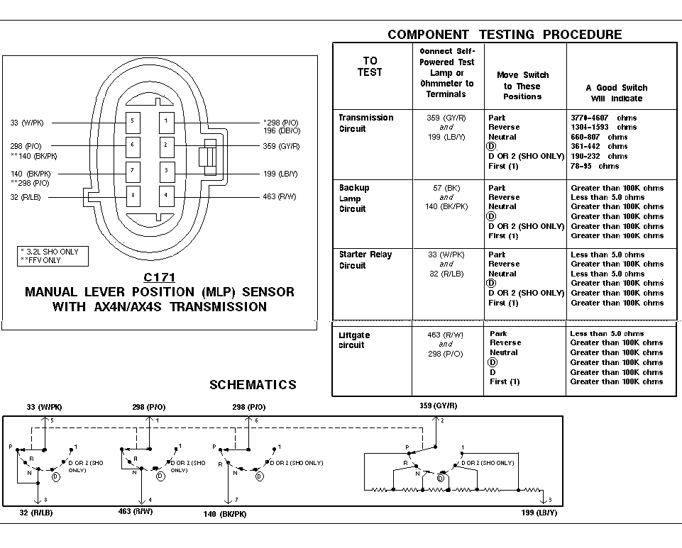
Ford AX4N/AX4S MLP Sensor (TRS) Test Procedure - C171 Pinout & Resistance Chart
Reference · 1992-1995 TaurusAll 12 service procedures

Manual lever position (MLP) sensor test procedure with connector pinout, ohmmeter test table, and switch schematics.
Part of 1992-1995 Ford Taurus Service Procedures
This service document covers testing of the Manual Lever Position (MLP) sensor, also known as the transmission range sensor, used with Ford's AX4N/AX4S automatic transmissions at connector C171. The left portion shows the 8-pin connector pinout with circuit numbers and wire colors: 33 (W/PK), 298 (P/O), 140 (BK/PK), 32 (R/LB), 196 (DB/O), 359 (GY/R), 199 (LB/Y), and 463 (R/W). Footnotes indicate some circuits apply only to the 3.2L SHO or FFV (flexible fuel vehicle). The Component Testing Procedure table gives ohmmeter/self-powered test lamp checks for four circuits, Transmission, Backup Lamp, Starter Relay, and Liftgate, listing which terminal pairs to probe, the shift positions to test (Park, Reverse, Neutral, D, D or 2 SHO only, First), and expected resistance values, such as 3770-4607 ohms in Park for the transmission circuit and less-than-5.0-ohm continuity for starter relay in Park/Neutral and backup lamps in Reverse. The bottom of the page shows internal schematics of the four switch circuits, including the resistor ladder on the 359/199 transmission-range circuit. A reader can diagnose no-start, backup lamp, liftgate release, and range-sensor faults using these specifications.
Is this accurate? Sign in to help verify it.
Frequently asked questions
- What resistance should the MLP sensor transmission circuit show in Park?
- Between terminals 359 (GY/R) and 199 (LB/Y), a good switch reads 3770-4607 ohms in Park.
- Which terminals test the starter relay circuit on the AX4S/AX4N MLP sensor?
- Connect a self-powered test lamp or ohmmeter to terminals 33 (W/PK) and 32 (R/LB). A good switch shows less than 5.0 ohms in Park and Neutral, and greater than 100K ohms in all other positions.
- How do I test the backup lamp circuit at the MLP sensor?
- Test between 57 (BK) and 140 (BK/PK). It should read less than 5.0 ohms in Reverse and greater than 100K ohms in all other gear positions.
- What is the connector pinout for the C171 MLP sensor?
- Pin 5 = 33 (W/PK), pin 6 = 298 (P/O) (**140 BK/PK for FFV), pin 7 = 140 (BK/PK) (**298 P/O for FFV), pin 8 = 32 (R/LB), pin 1 = *298 (P/O) / 196 (DB/O), pin 2 = 359 (GY/R), pin 3 = 199 (LB/Y), pin 4 = 463 (R/W). * = 3.2L SHO only, ** = FFV only.
- What should the liftgate circuit read at the MLP sensor?
- Between 463 (R/W) and 298 (P/O), it should read less than 5.0 ohms in Park and greater than 100K ohms in Reverse, Neutral, D, and First.






No comments yet.