Home/
Registry/
Pontiac/
Grand Prix/
1997-2003/
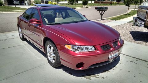
1997 Pontiac Grand Prix/
Photo
supermotors.net/registry/media/756817
Pontiac Grand Prix HVAC Air Delivery & Temperature Controls (C60) System Check

Reference · 1997-2003 Grand PrixAll 14 service procedures
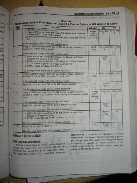
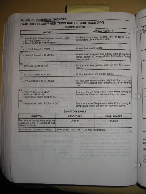


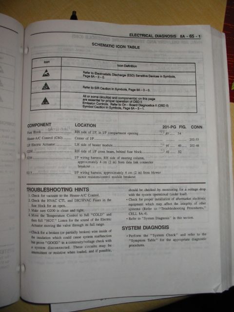

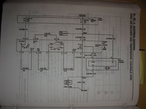


Ford electrical diagnosis (8A-65-2): HVAC air-delivery and temperature control (C60) system-check table listing action and normal results for MAX, VENT, BI-LEVEL, HEAT, BLEND and DEFROST plus symptom table.
Part of 1997-2003 Pontiac Grand Prix Service Procedures
This is a page (8A-65-2) from a GM service manual's Electrical Diagnosis section covering the HVAC Air Delivery and Temperature Controls system (RPO code C60). It provides a step-by-step SYSTEM CHECK table with eight numbered actions and the expected normal results for each. Steps include starting the engine to build vacuum supply, setting the HTR-A/C control to MAX, VENT, BI-LEVEL, HEAT, BLEND, and DEFROST positions, and rotating the Temperature Control Knob to HOT and COLD. Normal results describe expected airflow patterns from panel, floor, and defrost outlets, A/C engagement, and the audible sound of the Air Temperature Valve Motor rotating the Air Temperature Valve. A SYMPTOM TABLE at the bottom directs the technician: if the Temperature Control Knob does not cause air at outlets to get warmer or colder, use Chart #1 on page 8A-65-3; if air flow from outlets is incorrect, refer to Section 1-B for air flow diagnostics. A reader can use this page to verify correct HVAC mode-door and temperature control operation and determine which diagnostic procedure to follow when the system behaves abnormally.
Is this accurate? Sign in to help verify it.
Frequently asked questions
- How do I test if the HVAC temperature control system is working correctly?
- Perform the System Check: start the engine to build adequate vacuum supply, set the HTR-A/C Control to MAX with the blower on medium speed, then cycle through VENT, BI-LEVEL, HEAT, BLEND, and DEFROST modes, checking that air comes from the correct outlets. Then set VENT with blower on LO and rotate the Temperature Control Knob to HOT and COLD, listening for the Air Temperature Valve Motor rotating the valve and feeling warm or cool air flow.
- What should happen when the HTR-A/C control is set to DEFROST?
- Air flow should come from the defrost outlets with slight air flow from the floor outlets, and A/C should be engaged with the Temperature Control Knob to cold.
- What if the Temperature Control Knob does not make the air warmer or colder?
- The Symptom Table directs you to Chart #1 on page 8A-65-3.
- What should I do if air flow from the outlets is incorrect?
- Refer to SECTION 1-B for Air Flow diagnostics.
- What is the expected result in BI-LEVEL mode?
- Air flow from panel and floor outlets, slight air flow from defrost outlets, and A/C engaged with the Temperature Control Knob to cold.
No comments yet.