2000 Mitsubishi Montero Fuel Pump Assembly Removal Diagram & Torque Specs

Reference · 1992-2000 MonteroAll 4 exploded parts diagrams
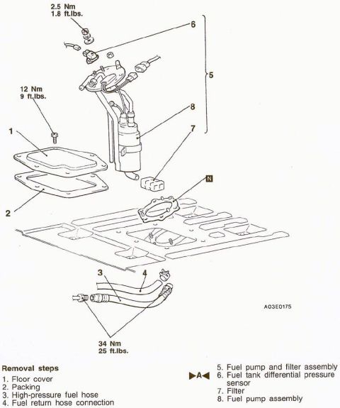
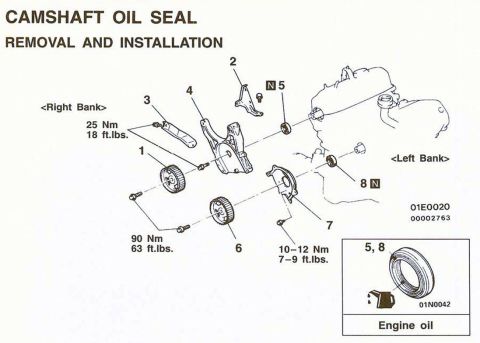
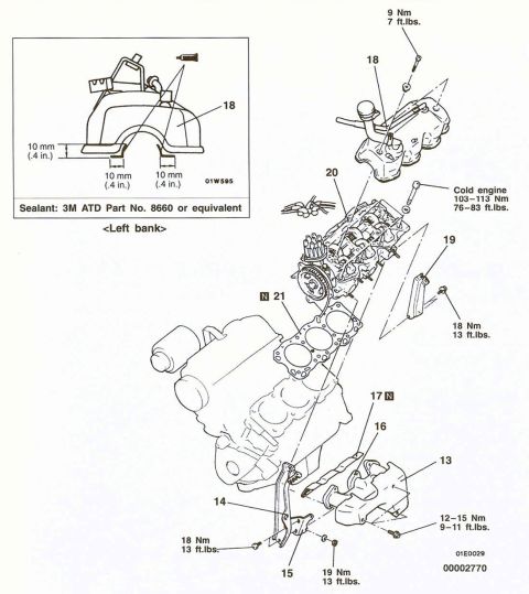
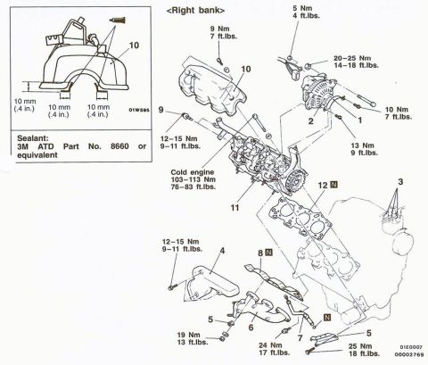
Exploded parts breakdown of the fuel pump assembly with numbered removal steps and torque specifications.
Part of 1992-2000 Mitsubishi Montero Exploded Parts Diagrams
This document is an exploded parts diagram showing the removal steps for a fuel pump and filter assembly, accessed through an interior floor cover above the fuel tank. The illustration identifies eight numbered components: (1) floor cover, (2) packing (gasket), (3) high-pressure fuel hose, (4) fuel return hose connection, (5) fuel pump and filter assembly, (6) fuel tank differential pressure sensor, (7) filter, and (8) fuel pump assembly. Item 6 carries a ▶A◀ marker, indicating a special installation/service note referenced elsewhere in the manual. Three torque specifications are shown: 2.5 Nm (1.8 ft.lbs.) for the differential pressure sensor fastener, 12 Nm (9 ft.lbs.) for the floor cover bolts, and 34 Nm (25 ft.lbs.) for the high-pressure fuel hose/return hose fittings. A boxed 'N' symbol on the tank mounting plate indicates a non-reusable part (gasket/packing). The figure reference number A03E0175 appears at the lower right. A reader can learn the order of disassembly, the components involved in the in-tank fuel pump module, and the correct tightening torques for reassembly. The scan was uploaded to a 2000 Mitsubishi Montero gallery; the diagram itself shows no year, model, or engine identification.
Is this accurate? Sign in to help verify it.
Frequently asked questions
- What are the removal steps for the fuel pump assembly?
- 1. Floor cover, 2. Packing, 3. High-pressure fuel hose, 4. Fuel return hose connection, 5. Fuel pump and filter assembly, 6. Fuel tank differential pressure sensor, 7. Filter, 8. Fuel pump assembly.
- What is the torque spec for the high-pressure fuel hose fittings?
- 34 Nm (25 ft.lbs.).
- What torque is used on the floor cover bolts?
- 12 Nm (9 ft.lbs.).
- What torque is specified for the fuel tank differential pressure sensor fastener?
- 2.5 Nm (1.8 ft.lbs.).
- How is the fuel pump accessed?
- Through a floor cover with packing (gasket) removed from inside the vehicle, above the fuel tank; the pump and filter assembly then lifts out of the tank opening.
No comments yet.