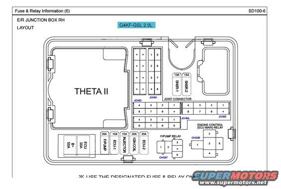
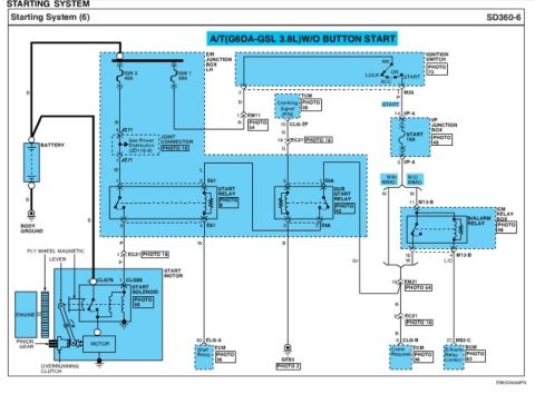
This diagram details the fuse and relay layout for the E/R junction box, including components like the Theta II engine control unit.
Fuse 3 Relay lnfmmalim m swan5 E/R JUNcnoN aox RH LAYOUT 44:? 1:? HE mmcmilsmk THETA || HE [EEE 77E- 3 3 __ H- m w_ v a: m: n:e|r:MAT=n :1 .e: e an Av muv
Comments
More from this build

No comments yet.