Home/
Registry/
International/
Scout/
1961-1965/
“Scugly”/
Photo
supermotors.net/registry/media/871532
4 Bar Linkage Calculator V3.0 - Long Link Droop Geometry, Anti-Squat & Roll Axis

Reference · 1961-1965 ScoutAll 13 schematics
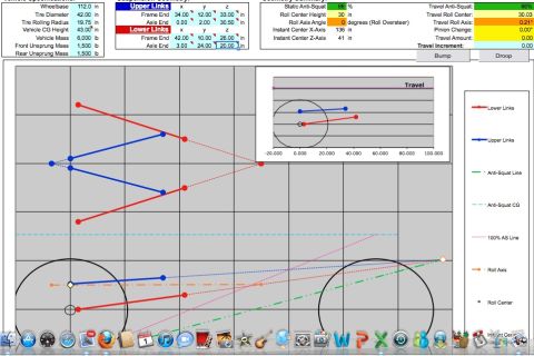
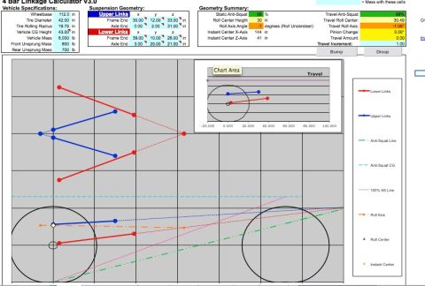
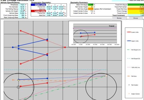
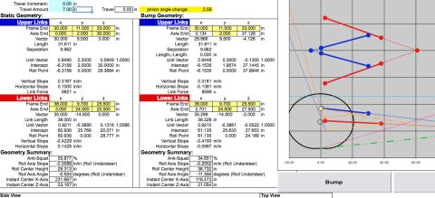
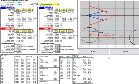
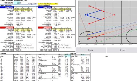
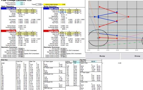
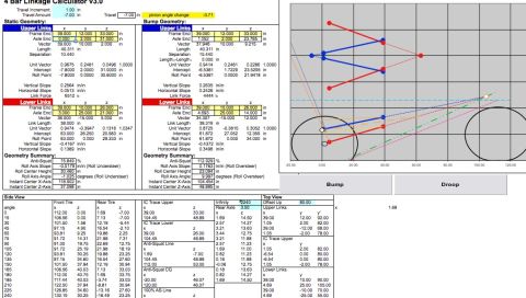
Suspension 4-bar linkage calculator spreadsheet showing geometry data tables and a plotted link/wheel geometry diagram.
Part of 1961-1965 International Scout Schematics
This document is a screenshot of a spreadsheet-based '4 Bar Linkage Calculator V3.0' used to design a four-link suspension, uploaded as one page ('longdroop.jpg') in a set of suspension design worksheets for a 1961 International Scout 800 project. It shows the linkage at -7.00 inches of travel (droop) with a pinion angle change of -3.71 degrees. Side-by-side 'Static Geometry' and 'Bump Geometry' panels list upper and lower link frame-end and axle-end coordinates (x, y, z), link vectors, lengths (upper 40.311 in, lower 38.000 in static / 39.319 in bump), unit vectors, intercepts, roll points, slopes, and link forces (6512 lb static, 4444 lb bump). Geometry summaries compare anti-squat (75.849% static vs 112.929% in droop), roll axis slope (-0.0179 in/in roll understeer static vs 0.1763 in/in roll oversteer), roll center height (30.460 in vs 23.094 in), roll axis angle, and instant center X/Z locations. A graphical side-view plot shows link positions, tire circles, and anti-squat/IC trace lines, with 'Bump' and 'Droop' buttons. Lower tables list side-view tire coordinates by angle (0-240 degrees), IC trace upper/lower points, anti-squat line and CG coordinates, and top-view link coordinates. A reader can learn the specific link coordinates and resulting suspension geometry behavior at full droop for this build.
Is this accurate? Sign in to help verify it.
Frequently asked questions
- What is the anti-squat percentage in the static versus droop (bump geometry) condition?
- The static geometry shows 75.849% anti-squat, while at -7.00 inches of travel the geometry summary shows 112.929% anti-squat.
- How much does the pinion angle change at -7.00 inches of travel?
- The calculator shows a pinion angle change of -3.71 degrees at a travel of -7.00 inches.
- What are the link lengths used in this 4-link setup?
- The upper links are 40.311 inches long and the lower links are 38.000 inches long (39.319 in shown in the bump geometry panel).
- Does this geometry produce roll understeer or roll oversteer?
- In static geometry it produces roll understeer (roll axis slope -0.0179 in/in, roll axis angle -1.025 degrees); at -7.00 in travel it produces roll oversteer (slope 0.1763 in/in, angle 9.997 degrees).
- What are the link forces shown?
- The upper link force is 6512 lb in static geometry and 4444 lb in the bump/droop geometry.

No comments yet.