Home/
Registry/
Ford/
Bronco/
1992-1996/
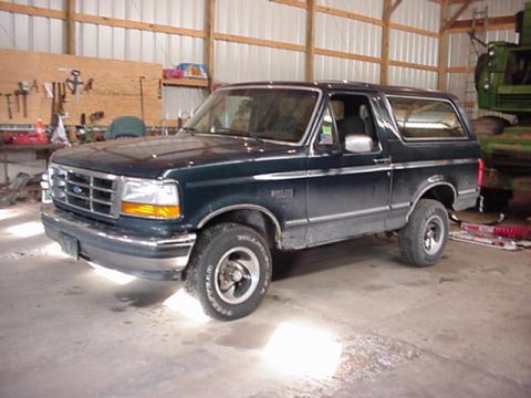
“pukin' dogII”/
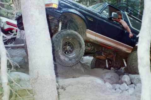
Photo
supermotors.net/registry/media/877870
Diagrams illustrate various engine control signals including IDM, SPOUT, PIP, and CCD waveforms, crucial for understanding ignition timing and diagnostics.
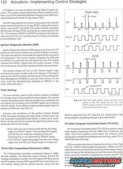
122 ActuatorsImplementing Control Strategies in chapter 5. you saw a typical Look-Up Tabla lor spark ad vance. The control module determines that lor certain condi- lions. say act kPa Manlleld Absolute Pressure and 2000 rpm. spark advance should he 32 deg. oelore Too. The PiP input signals the control module about rpm and the basic crankshall position ot lo deg. BTDC. Using other sensor inputs. such as ECT and EGO. the control module calculates the timing lor 32 deg, BTDC. and sends an output signal lo the TFl TFI compares SPOUT and PIP lor timing lo open the pn mary circuit lor the coil. causing ring ol one plug as selecled by the distrioutor rolor. Ignlllon Dlagnnsc Manltor (IDM) ignition Diagnoslic Monitor (IDM) signal is senl trom the TF1 Module to lhe control module as a check cl ignition iuncllnn. This uses the same pin that sends the signal lo the coil and to the toohorrieler. The control module compares the IBM with the SPOUT to verily that the can signal train the TH module matches the SPOUT signal train the control module it they are not lhe same. the ignition system prooaoly has some laull. The control module will turn on the Check Englne Light and slore the proper trouole cone in its memory. It the laull is serious. the control module will swttch over to Falluie Mode El- lerns Managemenl lFMEM) so you can drive home or to lhe shop. Ford has descnhed lhls checking as SPOUT is the shout, IBM is the echo " Push Starling For push starting. output ol the control module is modilied lorstroriger spark under conditions or low hallery. The control module recognizes push-sterling condition as a relalively low rpm signal. as it cranking. out no START signal. as il cranking wrlti lhe starlet. Posh staning mode pmvidas longer dwell lor grealerooil ON liriie. See Fig. 34. Compare lhe wovetorrns oi the Ignition Control Module (ICM), the uppershowing push-starl mode. anoihe lower, reg- uler Compuler-Conlnollad Dwell (ecu). In each set or wave- lonns. the lap set ol lines shows the spark liring lines as you would see them on the scope. - Push start: the coil is tired ltumed oil) by the rising edge ol a SPouT signal, This provides the Icngesl coil ON time lor maximum charging at the coil Charging lime is not controlled by SPDUT slgnal. - can: SPDUT signal rising edge tires the coil, Falling edge turns coil on. just long enough to charge coil TFI-IV with Closed-Bowl Dlstrlblor (CED) TFHV Closed Bowl identities e disliihutor design in team 90 3.5L engines. The distnoulor bowl is closed. and me TFI module is remotely mounted. One PIP signal (PIP-B) is sent to the TH module. Asecond PIF' signal (PIP-A) is sent to the cen- irol module. along with the ignition ground. along wrlh lhe Push Stan -Dwsll IDM _U_U'_U'_Lr sPou1 J : [ SignamlePlP _ f l l 1 l r CCD rDwell lDM A (FTC) L S TU . -WFi [.K SPOUT Slglaurs PIP aim AlSlmL W J Fig. 34. Pushsslan spark signals, upoer. tire pings whei ignition is ON, PlP signals are low rate and START signal IS missing Compare to Camm' Controlled Dwell lchi lower SPOUT signal lrom the TFI. See g, 375. These show in the wiring diagram as passing through a grounded shield. TFI with Computer-Controlled Dwell (TFI-CCD) TFI compulerontrolled Dwell (TFl-CCD) is used on some Ford engines. beginning with the 1939 5.0L in Calilornia. By 1952. mosl Ford systems control dwell, lhe minimum time necessary to charge the coiloelorerhe nextnnng, eitherTFl or DIS/EDIS teee lollowing). CCD computes the timing or closing the primary circuit See Fig. 3-5. in enact. COD answers the question. When must TFl close the prlniary circuit tor lhe next llring (which keeps chang ing its timing) so the coil primary cuneru can rise to the proper level iusl at the momenl or opening the primary circutli" For example. the higher the rpm. the sooner the primary circut must close to allow enough time to charge the coil. so cco in cludes inputs lrom PIP. ccn delivers less energy into the out to reduce overheating.
Comments
More from this build


No comments yet.