Home/
Registry/
Ford/
Bronco/
1992-1996/
“pukin' dogII”/
Photo
supermotors.net/registry/media/1138757
1996 Ford Bronco A/C-Heater Vacuum Routing Diagram - HVAC Door Vacuum Motors

Reference · 1992-1996 BroncoAll 40 vacuum routing diagrams


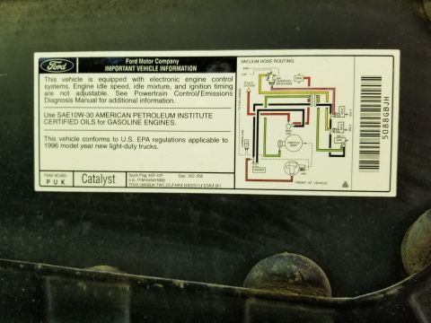
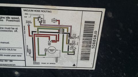
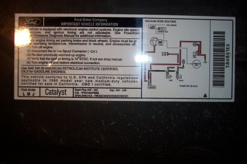
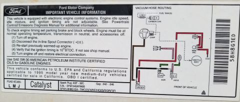








Vacuum routing diagram of the HVAC system showing color-coded hoses to door vacuum motors and control valves.
Part of 1992-1996 Ford Bronco Vacuum Routing Diagrams
This document is a vacuum routing diagram for an automotive A/C-heater (HVAC) system, uploaded as applying to a 1996 Ford Bronco. It traces vacuum supply from the manifold fitting through a vacuum check valve and vacuum tank (all black hoses) to the HVCB (Harness Vacuum Connection Block) and FCCB (Function Control Connection Block), which feed the A/C-heater function selector vacuum valve. The selector valve schematic shows its positions: OFF, MAX, NORM, VENT, FLOOR, MIX, and DEFROST. Color-coded vacuum lines route from the valve: red and yellow hoses to the floor-defrost door vacuum motor (ports A and B), blue hoses to the panel door vacuum motor, and white hoses to the outside/recirculate door vacuum motor. The lower half shows a cutaway of the HVAC plenum with the heater core, evaporator core, blower motor and wheel, suction accumulator/dryer, dash panel, and airflow paths to the defrosters, R & L demisters, floor outlets, and instrument panel registers. The temperature blend door is noted as cable controlled (not vacuum), and outside air from the cowl versus recirculated air is shown at the outside/recirc air door. A legend defines door position markings: V = vacuum, NV = no vacuum, PV = partial vacuum. Useful for diagnosing airflow stuck on defrost or incorrect vent selection.
Is this accurate? Sign in to help verify it.
Frequently asked questions
- What color vacuum hoses go to the floor-defrost door vacuum motor?
- Red and yellow hoses connect to the floor-defrost door vacuum motor, at ports labeled A and B in the diagram.
- What hose color operates the panel door vacuum motor?
- Blue vacuum hoses from the A/C-heater function selector valve operate the panel door vacuum motor.
- Is the temperature blend door vacuum operated?
- No. The diagram notes the temperature blend door is cable controlled by the temperature control lever.
- What do HVCB and FCCB stand for in this diagram?
- HVCB is the Harness Vacuum Connection Block and FCCB is the Function Control Connection Block.
- What do the V, NV, and PV markings mean?
- Per the legend: V = vacuum, NV = no vacuum, PV = partial vacuum, indicating the vacuum state that positions each air door.






No comments yet.