Home/
Registry/
Ford/
Fairlane/
1968-1969/
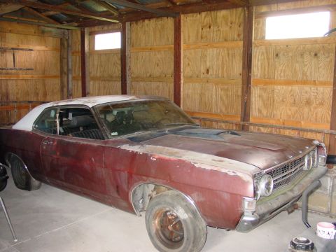
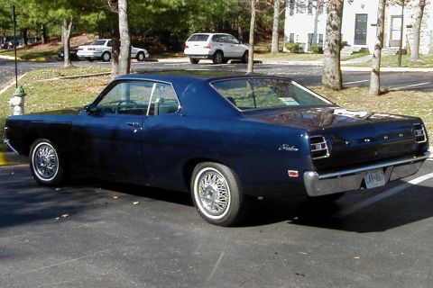
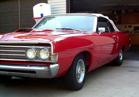
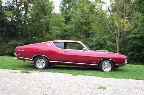
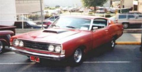
1969 Ford Fairlane/
Photo
supermotors.net/registry/media/895794
IPC Engine 2011 Fig 12a - Cutaway CAD of Pistons, Linkage Rods & Crankshaft

CAD render showing the crankshaft, connecting-rod and piston assembly with end gears of an engine.
This document is not a text schematic but a 3D CAD rendering of an unconventional internal combustion engine's reciprocating assembly, shown in cutaway. It shows four ported cylinder liners in cross-section, each containing sectioned pistons connected by an articulated linkage of multiple connecting rods per cylinder rather than a single rod. The rods converge onto a common crankshaft with large counterweights. Gear trains with idler gears and bushings are visible at both ends of the crankshaft, presumably driving auxiliary or balance/phasing shafts, and a large flywheel with lightening holes is mounted at one end. The cylinder liners show rows of ports machined through their walls, suggesting port-controlled gas exchange (as in two-stroke or extended-expansion designs). A reader can learn the general mechanical layout and kinematic arrangement of this engine concept, the relationship between pistons, multi-link connecting rods, crankshaft, gear train, and flywheel, but no textual data: there are no part numbers, dimensions, torque specifications, or labels anywhere in the image. Based on the filename it appears to be figure 12a from a 2011 'IPC engine' figure set, part of a multi-page album of related engine-concept figures, and it is not specific to any production vehicle.
Is this accurate? Sign in to help verify it.
Frequently asked questions
- What does this diagram show?
- A 3D cutaway CAD rendering of an engine's reciprocating assembly: four ported cylinder liners with sectioned pistons, multiple connecting rods per cylinder in an articulated linkage, a counterweighted crankshaft, gear trains at both ends, and a flywheel with lightening holes.
- Are there any part numbers, torque specs, or labels in this document?
- No. The image contains no visible text, labels, callouts, dimensions, or part numbers of any kind.
- How many cylinders are shown?
- Four cylinder liners are shown, each cut away to reveal the pistons and linkage inside.
- Does each piston use a single connecting rod?
- No. The rendering shows multiple connecting rods per cylinder arranged in an articulated linkage between the pistons and the crankshaft.
- What other major components are visible?
- A brown crankshaft with counterweights and a bolted end flange, meshing gears with yellow bushings at both ends of the crank, and a large blue flywheel with holes at the right-hand end.
Comments
More from this build
No comments yet.