Home/
Registry/
Ford/
Fairlane/
1968-1969/
1969 Ford Fairlane/
Photo
supermotors.net/registry/media/895804
IPC Engine 2011 Fig 20a - Piston & Connecting Rod CAD Cross-Section Diagram

Reference · 1968-1969 FairlaneAll 22 schematics
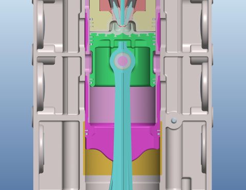
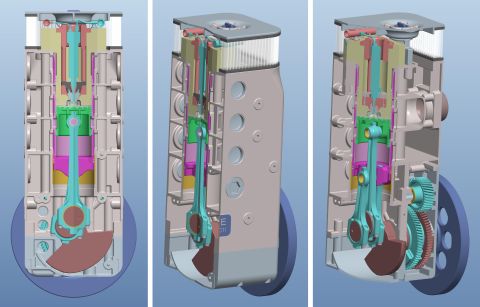
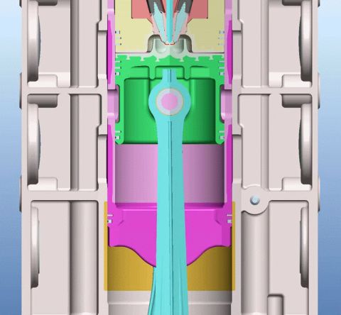
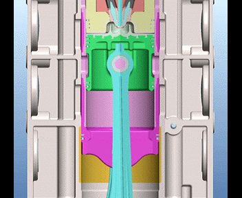
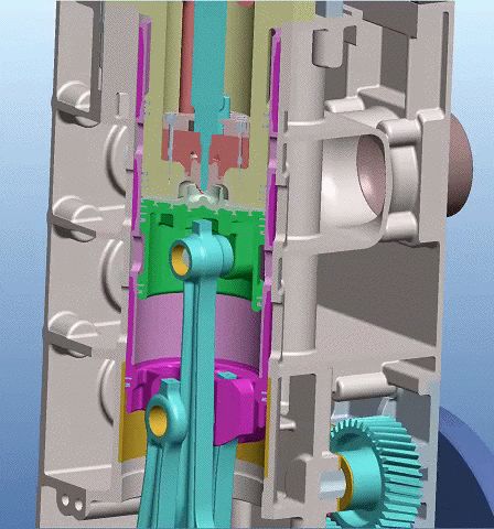

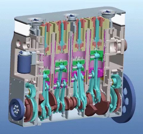
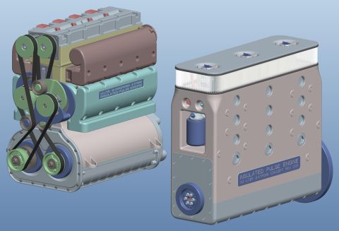

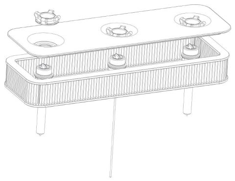
CAD cross-section schematic of a single engine cylinder with piston, valves and connecting rod.
Part of 1968-1969 Ford Fairlane Schematics
This document is a color CAD-style cross-sectional illustration, apparently a figure (labeled 'fig20a' in the filename) from a series about internal combustion engine design. The image shows a vertical section through an engine cylinder assembly: a piston (rendered in green) with rings at top dead center or mid-stroke, connected via a wrist pin to a long connecting rod (rendered in cyan/teal) extending downward. Above the piston is a combustion chamber region with what appears to be a fuel injector or spark plug assembly (rendered in red/orange and yellow tones) at the cylinder head. Surrounding structures in gray and magenta represent the cylinder block, liner, and casing. The illustration contains no visible text, legends, dimensions, or part numbers, so no technical specifications can be transcribed. A reader can learn the general internal arrangement of this engine concept, piston, rings, wrist pin, connecting rod, and head-mounted component, from the visual alone. Based on companion filenames in the album (referencing 'IPC engine' and Chatterton hyper-expansion patents), this appears to relate to an unconventional or experimental engine design concept rather than a specific production vehicle component.
Is this accurate? Sign in to help verify it.
Frequently asked questions
- Does this diagram contain any part numbers or specifications?
- No. The image is a purely graphical CAD cross-section with no visible text, labels, part numbers, dimensions, or torque values.
- What does this figure show?
- A vertical cross-section of an engine cylinder assembly, showing a piston with rings, a wrist pin, a long connecting rod, the cylinder block/liner structure, and a component mounted at the cylinder head above the combustion chamber.
- Is this a wiring or fuse diagram?
- No. Despite being classified as a schematic, it is a mechanical engine cross-section illustration, not an electrical diagram.
No comments yet.