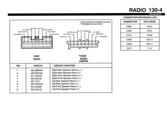
This diagram details the wiring for the radio, including connector pinouts and circuit functions.
805 (W/LG) 801 (rm * (NOT USED WITH PREMIUM SOUND) ** (PREMIUM SOUND ONLY) RADIO 130-4 1995 BRONCO CONNECTOR REFERENCE LIST CONNECTOR CELL-PAGE 0200 150-3 C202 150-4 C214 150-9 0228 150-10 C229 150-1 1 C273 1 71-2 811 (DG/O) -807 (PK/LG) 806 (PK/LE1 813 (LB/W) 807 (PK/LG) 801 (TM 805 (W/LG) 811 (DG/O) 803 (BR/PK) - -804 (O/LG) 813 (LB/W) 806 (PK/LB) {- 804 (one) 803 (BR/PK) 1:1 1:1 1:1 [:1 1: c: l I'] " F] l 1 2 3 4 56 a Llreiangugf 8 7 6 5 4 3 2 1 U "' U m **C_25 RADIO RADIO JUMPER PIN CIRCUIT CIRCUIT FUNCTION 1 803 (BR/PK) Right Rear Speaker Return () 2 806 (PK/LB) Right Rear Speaker Feed (+) 3 811 (DG/O) Right Front Speaker Return () 4 805 (W/LG) Right Front Speaker Feed (+) 5 801 (T/Y) Left Rear Speaker Return () 6 807 (PK/LG) Left Rear Speaker Feed (+) 7 813 (LB/W) Left Front Speaker Return (~) 8 804 (O/LG) Left Front Speaker Feed (+)
Comments
More from this build


No comments yet.