1995 Ford Bronco Radio Wiring Diagram - C257 Connector Pinout (Page 130-3)

Reference · 1987-1991 BroncoAll 175 wiring diagrams

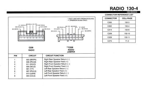
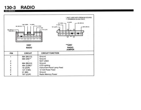
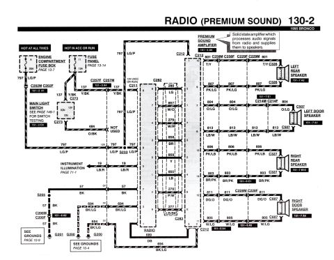
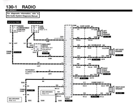
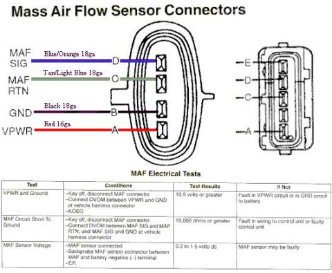
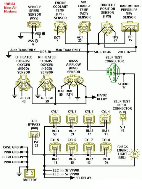












Radio C257 connector pin-out diagram for a 1995 Bronco with a table listing each pin's circuit number and function.
Part of 1987-1991 Ford Bronco Wiring Diagrams
This document is page 130-3 of the 1995 Ford Bronco factory wiring reference, covering the RADIO system. It shows connector face views and a pinout table for connector C257, in two variants: the standard C257 RADIO connector and the C257 RADIO JUMPER used with Premium Sound. Footnotes indicate circuit 484 (O/BK) is not used with Premium Sound (*) and circuit 689 (DB) is Premium Sound only (**). The pinout table lists all eight pins: Pin 1-694 (BK/LG) Ground (or 689 (DB) Ground on Premium Sound); Pin 2: Not Used; Pin 3-694 (BK/LG) Ground; Pin 4-484 (O/BK) LCD Lighting; Pin 5-19 (LB/R) Instrument Panel Lamp Feed; Pin 6-137 (Y/BK) 12 Volt Power Feed; Pin 7-57 (BK) Ground; Pin 8-797 (LG/P) Radio Memory Power. Wire colors are given as circuit number plus color code (e.g., BK/LG = black/light green, LG/P = light green/purple). A reader can use this page to identify radio harness wires by pin, circuit number, color, and function, useful for aftermarket stereo installation or diagnosing radio power, memory, illumination, and ground circuits on a 1995 Bronco.
This document covers 1995, which may differ from this 1990 Ford Bronco.
Is this accurate? Sign in to help verify it.
Frequently asked questions
- What is the radio connector number on a 1995 Ford Bronco?
- The radio connector is C257. A second C257 'Radio Jumper' connector view is shown for Premium Sound applications.
- Which pin is the 12 volt power feed on the 1995 Bronco radio connector?
- Pin 6, circuit 137 (Y/BK: yellow/black), is the 12 Volt Power Feed.
- Which wire keeps the radio memory alive on a 1995 Bronco?
- Pin 8, circuit 797 (LG/P: light green/purple), is Radio Memory Power.
- Which pins are grounds on the 1995 Bronco radio connector?
- Pin 1 (694 BK/LG, or 689 DB on Premium Sound), Pin 3 (694 BK/LG), and Pin 7 (57 BK) are grounds.
- What is the LCD lighting circuit on the 1995 Bronco radio?
- Pin 4, circuit 484 (O/BK: orange/black), is LCD Lighting; the footnote states it is not used with Premium Sound.






No comments yet.