SuperMotors SuperMotors SUPERMOTORS Search — try “orange Bronco on 35s”
Home/ Registry/ Ford/ Bronco/ 1992-1996/ “Buckin Bronco”/ Photo supermotors.net/registry/media/984834

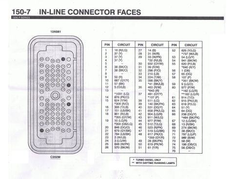
In-line connector faces pinout diagram for 1996 F-Series C202M c…

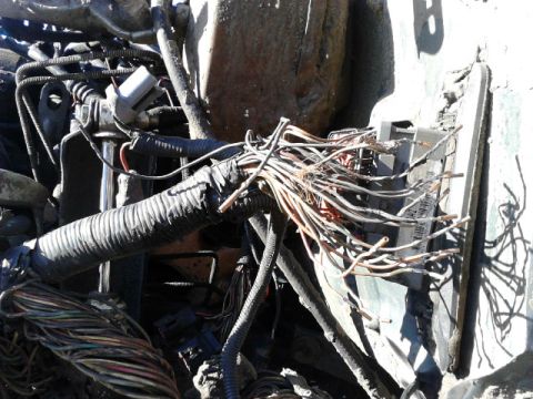
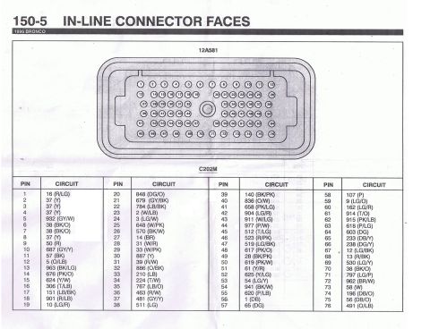
The pinout of main firewall connector (C202 connector) for a 96 F-Series truck (NOT including Bronco). It has a slightly different pinout than the Bronco connector which can cause problems if interchanged like I found out.


Most pins are the same between the 2 which allows the engine to run and most thing work. main differences I have found are from 4WABS pin locations (including the VSS signal wires which will affect automatic trannys).

Different years also seem to have different pinouts based on Steve83's diagram of a 93s connector, you can also use his diagram to find out what MOST of the circuits stand for. view it here

Owner caption · Photo 130 of 386

Is this accurate? Sign in to help verify it.

Comments

No comments yet.

More from this build

Ford 5.8L California engine controls wiring diagram page 25-12, inertia fuel shutoff and fuel pump module Ford 5.8L California engine controls wiring diagram page 25-11, malfunction indicator lamp and HO2S Ford 5.8L California engine controls wiring diagram page 25-10, IAT sensor and heated oxygen sensor Ford 5.8L California engine controls wiring diagram page 25-9, EGR, ECT, TP and EGR valve position sensors Ford 5.8L California engine controls wiring diagram page 25-8, fuel injectors and idle air control circuits Ford 5.8L California engine controls wiring diagram page 25-7, PCM power relay and fuel pump circuits Vehicle Speed Sensor (VSS) wiring diagram, Bronco, page 64-2, rear axle sensor and PSOM circuits Vehicle Speed Sensor (VSS) wiring diagram, F-Series, page 64-1, rear axle sensor and PSOM circuits

More 1992-1996 Broncos