1992-96 Ford Sealed-Bowl TFI Distributor Diagram & Ignition Wiring Schematics
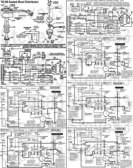
Ford EVTM page: '92-96 sealed (closed) bowl distributor with computer-controlled dwell, showing the ICM/PCM ignition wiring, PIP/SPOUT/IDM circuits, diagnostic breakout-box test jacks and Hall-effect stator across multiple gasoline-engine diagrams.
This document is a multi-panel Ford reference sheet covering the 1992–1996 sealed-bowl (closed-bowl) TFI/CCD distributor and its ignition wiring. The top-left panel shows exploded assembled and disassembled views of the sealed-bowl distributor, labeling the shaft, screws, rotary vane, Hall effect vane stator switch (Profile Ignition Pickup / PIP), octane rod, rotor (with a note to coat the rotor blade tip with 1/32" silicone compound), O-ring, gear, pin, and base assembly. Two breakout-box connector diagrams cover System D (remote-mounted closed-bowl, push start, gray ICM) and System H (remote-mounted closed-bowl, Computer Controlled Dwell, black ICM), giving ICM pinouts, CMP/PIP sensor pin numbers, test-jack numbers, and wire colors (Gy/Or PIP, Pk SPOUT, R/LG, Tn/Y coil−, Bk/Wh ground, Wh/Pk tach). Five year-specific gasoline schematics (1992 Push-Start D, 1993/1993½ 5.0L CCD H, 1994 CCD H, 1995 CCD H, 1996 CCD H) show full circuits from the PCM/EEC module through the SPOUT check connector, ignition control module, distributor ignition shield, radio capacitor, ignition coil, and 20A HOT-IN-START-OR-RUN fuse feed, with circuit numbers (395 GY/O, 259 O/R, 570 BK/W, 648 W/PK, 938 BK/LG, 929 PK), connector IDs (C1021, C1019, C1008, C1017, C101, C178), and functional callouts. A reader can trace TFI ignition wiring and identify distributor components for these years.
This document covers 1992-1996, which may differ from this 1990 Ford Bronco.
Is this accurate? Sign in to help verify it.
Frequently asked questions
- What years does this sealed-bowl distributor diagram cover?
- The document is titled '92-96 Sealed-Bowl Distributor and includes year-specific ignition schematics for 1992 (Push-Start D), 1993/1993½ 5.0L CCD H, 1994, 1995, and 1996 CCD H gasoline systems.
- What is the ICM connector pinout for the closed-bowl TFI system?
- For System D (gray ICM): pin 1 PIP (Gy/Or), pin 2 SPOUT (Pk), pin 3 START (R/LG), pin 4 COIL− (Tn/Y), pin 5 ICM PWR, pin 6 GND (Bk/Wh), with TACH on Wh/Pk. For System H (black ICM), pin 3 is IDM (R/LG) instead of START, and ground is Bk/LG or Bk/Wh.
- What fuse powers the TFI/distributor ignition circuit?
- Each year's schematic shows a 20A fuse in the Engine Compartment Fuse Box (page 13-5), labeled HOT IN START OR RUN, feeding the 16 R/LG power circuit.
- What does the ignition control module (ICM) do according to this diagram?
- It receives the SPOUT (or PIP and SPOUT) signal from the PCM and uses it to switch current on and off in the primary circuit of the ignition coil; without the SPOUT it runs on the PIP at base timing.
- How much voltage does the ignition coil produce per the diagram notes?
- Each interruption of the primary current makes the ignition coil secondary circuit produce an open-circuit high-voltage pulse of up to 40,000 volts, transmitted to the distributor on the coil wire.
- What is the ignition suppression resistor part number shown?
- The 1992 and 1993 schematics show a 22KΩ ignition suppression resistor, part number E90B-14A601-EA.
Comments
More from this build













No comments yet.