Ford V8 & 6-Cylinder Firing Order Diagrams - 351/400 V8, Other V8, Inline Six

Reference · 1987-1991 BroncoAll 111 schematics
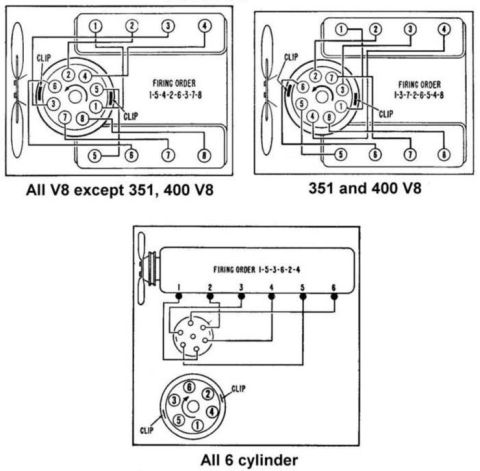









Ford firing-order and distributor cap wiring diagrams for V8 (351/400 and others) and 6-cylinder engines.
Part of 1987-1991 Ford Bronco Schematics
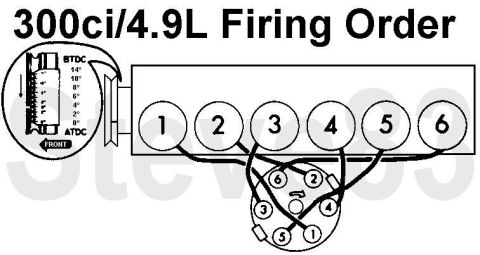
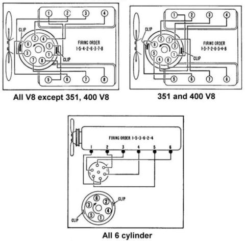
This document is a scanned schematic page showing spark plug wire routing and firing orders for three Ford engine families. The top-left diagram covers all V8 engines except the 351 and 400 V8, showing a firing order of 1-5-4-2-6-3-7-8 with the distributor cap terminal layout, clip locations, and wire routing from the cap to cylinders 1-4 on one bank and 5-8 on the other. The top-right diagram covers the 351 and 400 V8 engines, with a firing order of 1-3-7-2-6-5-4-8 and its corresponding cap layout and clip positions. The bottom diagram covers all 6-cylinder (inline six) engines, showing firing order 1-5-3-6-2-4, the wire routing from the distributor to cylinders 1 through 6 along the engine, and a detail view of the distributor cap terminal numbering with clip locations. Each diagram includes the fan/engine front orientation so the reader can identify cylinder numbering and correctly route plug wires. A reader can learn the correct firing order for their engine type, which distributor cap tower connects to which cylinder, and where the cap retaining clips are located. No years, part numbers, or wire colors are stated in the document itself.
Is this accurate? Sign in to help verify it.
Frequently asked questions
- What is the firing order for Ford V8 engines except the 351 and 400?
- According to the diagram, all V8 engines except the 351 and 400 V8 use firing order 1-5-4-2-6-3-7-8.
- What is the firing order for the Ford 351 and 400 V8?
- The diagram shows the 351 and 400 V8 firing order as 1-3-7-2-6-5-4-8.
- What is the firing order for Ford 6-cylinder engines?
- The bottom diagram shows all 6-cylinder engines use firing order 1-5-3-6-2-4.
- Does the diagram show how the spark plug wires route from the distributor cap?
- Yes. Each diagram shows lines from the numbered distributor cap towers to the numbered cylinders, plus the locations of the distributor cap clips.
- How are the cylinders numbered on the V8 diagrams?
- Cylinders 1-4 are on one bank and 5-8 on the other, numbered front to rear, with the fan indicating the front of the engine.






No comments yet.