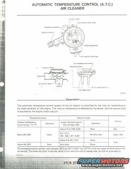
This diagram illustrates the operation of an automatic temperature control air cleaner system, detailing its components and functions.
7 AUTOMATIC TEMPERATURE CONTROL (A.T.C.) til AIR CLEANER P.C.Vt inter Air inlet for A3. vule Tamperatur- sonic" Vacuum meror ldln mmponsatur Alt trunnion valve Ilsa Air temperature elm-ml Vacuum motor r . #7: a _ - Yo intake manifaH Air ulna vulva SEF32 Operation The automatic temperature control system of the air cleaner is controlled by the inlet air temperature ar the load condition of the engine. The inlet air temperature is detected by the sensor, and the vacuum mott is actuated by the engine intake vacuum. Temperature sensor Vacuum motor Ambient temperature 0 r Intake manifold vacuum 0 erat '"m 5" around sensor 6 (Fl 3 '" kp. (mmHg, ian) " Above 21.3 (160, 6.30) Raise Hat 5.3 - 21.3 , . Below 38 (100) Close (40 A 160, 1-57 _ 6.30) Partially raise Gold + Hot Below 5.3 (40, 157) Down V , Cold Above 53 (up) Open Any value Down The temperature sensor partially opens bemenasw and 53C 00F and 127 F) so that the intake manifold vacuum may be reduoegiThis causes the motor to activate; which in turn opens the cold air passage wide. for cold air to be taken in. atone; , . ,7,
Comments
More from this build


No comments yet.