Home/
Registry/
Nissan/
Micra/
1983-1992/
1990 Nissan Micra/
Photo
supermotors.net/registry/media/294135
1990 Nissan Micra Wiring Diagram - Gauges, Warning Lamps, Wiper & Heater Circuits

Reference · 1983-1992 MicraAll 23 wiring diagrams



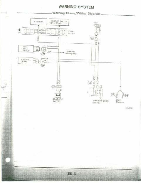

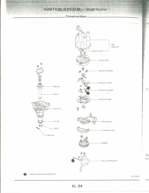
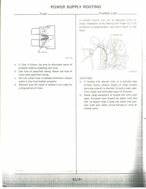
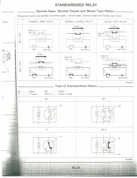
Vehicle wiring diagram showing fuses, switches, motors, relays and connectors across multiple circuits.
Part of 1983-1992 Nissan Micra Wiring Diagrams
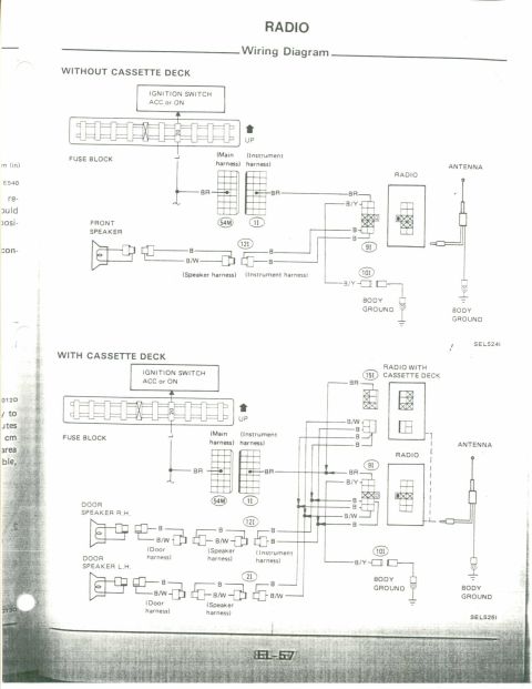
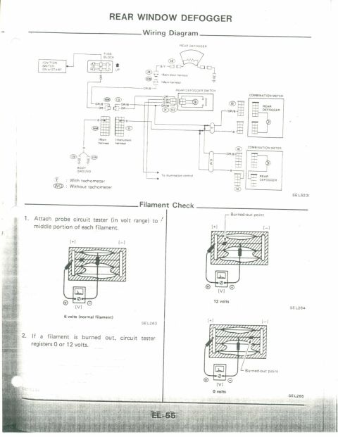
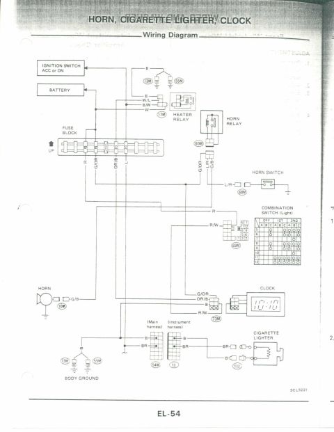
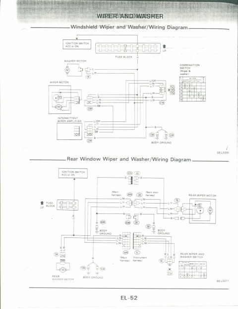
This document is a scanned page of a factory-style electrical wiring diagram, uploaded as applying to a 1990 Nissan Micra. The page contains three horizontal wiring schematics. The top circuit covers warning and gauge systems: charge warning lamp, power steering oil pressure switch, thermo switch, radiator fan motor, thermal transmitter, fuel tank gauge unit, temperature/fuel gauges (V/R), parking brake and brake fluid level switches, back-up lamps, inhibitor switch (A/T), oil pressure switch and warning lamp, seat belt timer/switch/warning lamp, chime, steering lock switch, door switch, rear defogger and switch, tachometer, and a 2.2 kΩ resistor. The middle circuit shows illumination and interior lighting: illumination control unit, meter, radio, heater control and A/T indicator illumination, stop lamps (LH, RH, high-mounted), room lamp, door switches, luggage compartment lamp, and a check connector detail showing IGN, body ground, automatic choke, and throttle opener terminals (positions 1, 7, 11, 12). The bottom circuit covers accessory items fed by FUSE-ACC: front wiper/washer switch and motors (OFF/INT/LO/HI), intermittent wiper amplifier (6-pin), rear wiper and washer switch/motor, radio, cigarette lighter, heater relay, blower motor, resistor, and fan switch (OFF/LO/M1/M2/HI). Circled letters (A, B, D, F, H, I, M, R, Y) mark inter-page circuit connections; grounds are marked 55M.
Is this accurate? Sign in to help verify it.
Frequently asked questions
- What fuses feed these circuits on the Nissan Micra wiring diagram?
- The gauge/warning lamp circuits are fed by FUSE-IG (shown at three points on the top diagram), while the wiper, washer, radio, cigarette lighter, heater relay and blower motor circuits are fed by FUSE-ACC.
- What positions does the Micra wiper switch have?
- The wiper & washer switch table shows OFF, INT, LO, and HI positions plus a washer position; an intermittent wiper amplifier with a 6-pin connector (pins 1-6) controls the INT function.
- What positions does the heater fan switch have?
- The fan switch table shows OFF, LO, M1, M2, and HI positions, working with the heater relay, resistor, and blower motor. One switch position row is marked 'Not used'.
- What is on the check connector shown in this diagram?
- The check connector detail shows terminal 1 (IGN.), terminal 7 (automatic choke), terminal 11 (throttle opener), and terminal 12 (body ground), with an arrow indicating the check terminal.
- What resistor value is used with the tachometer circuit?
- A 2.2 kΩ resistor is shown at the right side of the top circuit near the tachometer.


No comments yet.