This document details the inspection and adjustment procedures for a carburetor, including related electrical relay diagrams.
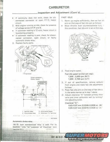
l W CARBURETOR I If continuity does not exist, check for dis connected connector or open. P.T.C. heater circuit. 2. With engine running at idle, check for presence ofvoltage across GY/R and B. 0 If voltmeter reading is 12 volts, heater circuit is functioning properly. 0 If voltmeter reading is zero, check for discon- nected connector, open circuit, or faulty automatic choke relay. 3. Replace faulty parts. Function check connector / 1 212m connector (Color: black) L a Au'taehokn'num 4 Alternator ' 'rlrminal 1 Ignition niav 2 Aumchaklrelav SEF3&B Automatic choke relay ' , 1MLIB,.WPE standardized- relay is used. For its locafianfL'refer Lit:r"Loi:aticin 6f Electrical Unit (mi .4! mm: : ; e; Inspection and Adjustment (Contd) FAST IDLE 1, Warm up engine sufficiently, then set fast idl- arm on 2nd step of fast idle cam as follows: 0 Move throttle lever counterclockwise fully. i this condition, fast idle arm is set at 2nd step. Move fully. 52H: 2. Read engine speed Fast idle speed (at 2nd cam step): 1,890 2,600 rpm (MIT) 1,900 - 2,700 rpm (AN) 3. if out of specifications, remove carbure! from engine and make fast idle adjustment: follows: 1) Place fast idle arm on 2nd step of fast idle ca in the same manner as in step 1 above. 2) Adjust clearance "A" between primary throt valve and inner carburetor wall by turningf idle adjusting screw. Clearance'A: 0.63:0.07 mm (0.0248t0.0028 in) (MI' 0.80:0.07 mm (00315310028 in) iAr'
Comments
More from this build


No comments yet.