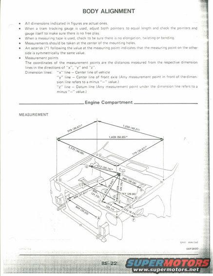
Diagram illustrating body alignment measurements for an engine compartment.
BODY ALIGNMENT All dimensions indicated in figures are actual ones. When a tram tracking gauge is used, adjust both pointers to equal length and check the pounters and gauge itself to make sure there is no free play. When a measuring tape is used, check to be sure there is no elongauonl twisting or bending, Measurements should be taken at the center of the mounting holes. 0 An asterisk ('l following the value at the measuring point indicates that the measuring point on the other side is symmetrically the same value. I Measurement points The coordinates of the measurement points are the distances measured from the respective dimension lines in the directions of ,x "y" and ".z Dimension lines: x" ne Center line of vehicle "y" line Center line of front axle (Any measurement point in front of thedimen sion line refers to a minus " value.) "z" line Datum line (Any measurement point under the dimension line refers toa minus "" value.) Engine Compartment MEASUREMENT Unlt: mm (In) ~ -' sanaao
Comments
More from this build


No comments yet.