SuperMotors SuperMotors SUPERMOTORS Search: try “orange Bronco on 35s”
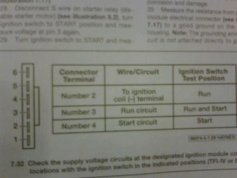
TFI ignition module connector terminal chart with pins 1-6 and ignition switch test positions

1986 Ford Ranger

documented by theramsey3 10 photos documented since 1 years documented ♡ Follow this build

Photos

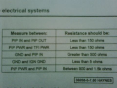
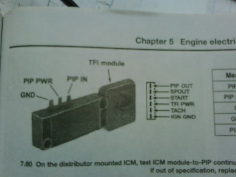
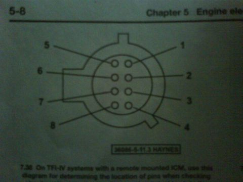
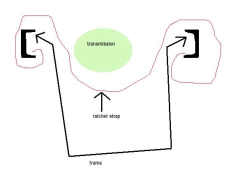
TFI ignition module connector terminal chart with pins 1-6 and ignition switch test positions TFI ignition module resistance chart for PIP IN, PIP OUT, PIP PWR, TFI PWR and ground terminals Service manual page, Chapter 5 Engine electrical, showing TFI module with pin labels Haynes manual page 5-8 showing an 8-pin connector pinout diagram for TFI-IV systems Digital multimeter with red and black leads connected, displaying 02.7 1986 Ford Ranger: Lifted pickup truck with large tires and chrome wheels, dark red paint Simple diagram of a transmission supported by a ratchet strap on a frame White electrical connector with red and white wires attached, lying on a blue card with text and a Dorman logo hand holding a white electrical connector on a blue card with red and white wires Blue package with white and red wires and a white connector

Albums · 2

How the owner organised this build. Open an album for every photo in it.

Technical reference · 1983-1992 Ford Ranger

Factory documentation members uploaded for this generation, sorted by how much of it there is.

The peanut gallery

No comments yet. Be the first to add to the record.

Spotted in the wild

Seen this vehicle at a show or on the trail? Add your shot. The owner approves it onto the record.