Home/
Registry/
Ford/
Ranger/
1983-1992/
1986 Ford Ranger/
Photo
supermotors.net/registry/media/828798
Transmission Removal Method Diagram - Ratchet Strap Support Sling Sketch

Reference · 1983-1992 RangerAll 6 schematics
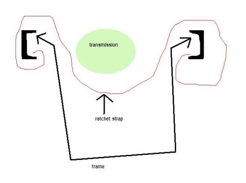
Labeled illustration showing a transmission held by a ratchet strap looped under a frame.
Part of 1983-1992 Ford Ranger Schematics
This is a simple hand-drawn (computer sketch) schematic illustrating a DIY method for supporting or lowering a transmission during removal using a ratchet strap. The drawing shows a green oval labeled 'transmission' cradled in a red outline representing the strap path. A black line labeled 'frame' runs beneath, with arrows at each end pointing to two black hook symbols (drawn as bracket shapes) at the upper left and right, indicating that the ratchet strap hooks attach to points on either side above/beside the transmission. An arrow labeled 'ratchet strap' points to the sling portion under the transmission, showing the strap looping under the transmission belly to act as a cradle. The concept conveyed: hook the ends of a ratchet strap to the vehicle frame (or crossmember points) on both sides, run the strap under the transmission, and use the ratchet to control the transmission's weight while unbolting and lowering it. The document contains only three text labels and no part numbers, torque specs, year/model applicability, or measurements. It was uploaded to a 1986 Ford Ranger gallery as 'trans removal method.jpg', but the sketch itself is generic and does not identify any specific vehicle.
Is this accurate? Sign in to help verify it.
Frequently asked questions
- What does this diagram show?
- It shows a method of supporting a transmission with a ratchet strap: the strap loops under the transmission like a cradle, with its hooks attached to points connected to the frame on either side.
- What tool is used to support the transmission in this method?
- A ratchet strap, run under the transmission and hooked at both ends.
- Where do the strap ends attach according to the sketch?
- The arrows from the line labeled 'frame' point to hook symbols on both sides, indicating the strap ends hook to points associated with the frame on each side of the transmission.
- Does the diagram give any torque specs, part numbers, or vehicle-specific details?
- No. The only text in the drawing is 'transmission', 'ratchet strap', and 'frame'.
No comments yet.