Home/
Registry/
Ford/
Ranger/
1983-1992/
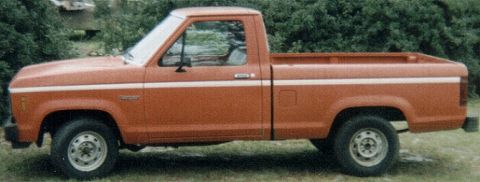
1986 Ford Ranger/
Photo
supermotors.net/registry/media/820399
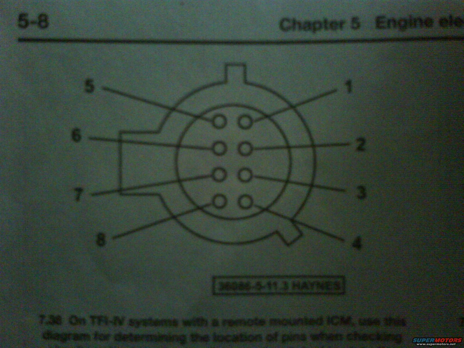
Ford TFI-IV Remote ICM 8-Pin Connector Pinout Diagram - Haynes Manual Page 5-8
Reference · 1983-1992 RangerAll 3 manual pages
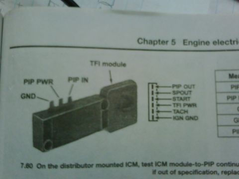
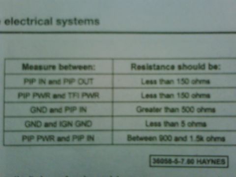
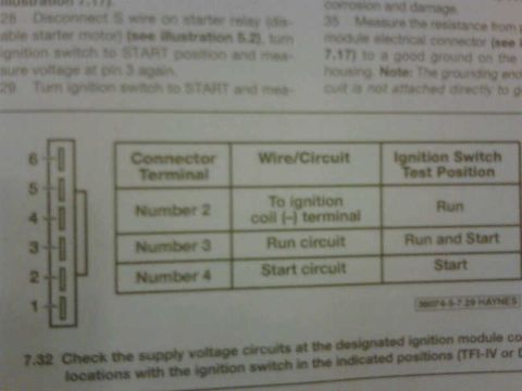
Haynes service manual page showing a numbered 8-pin connector pinout diagram for TFI-IV ignition systems.
Part of 1983-1992 Ford Ranger Manual Pages
This is a scanned page (page 5-8) from a Haynes repair manual, Chapter 5, 'Engine ele[ctrical systems]' (title partially cut off). The page shows illustration 7.36, a pin-location diagram for the connector used on TFI-IV ignition systems that have a remote-mounted ICM (Ignition Control Module). The drawing depicts the 8-pin connector viewed face-on: two vertical columns of four round pin cavities inside a keyed circular connector body. Callout numbers identify the pin positions, pins 5, 6, 7 and 8 on the left column (top to bottom) and pins 1, 2, 3 and 4 on the right column (top to bottom). The figure carries the Haynes illustration reference number '36086-5-11.3 HAYNES'. The caption instructs the reader to use this diagram to determine the location of the pins when checking the module/harness (the last line of the caption is cut off at the bottom of the scan). A reader can use this page to correctly identify pin numbers 1 through 8 on the remote-mounted TFI-IV ICM connector before performing electrical checks described elsewhere in the chapter.
Is this accurate? Sign in to help verify it.
Frequently asked questions
- What does this Haynes manual diagram show?
- It shows figure 7.36, a pin-location diagram for the connector on TFI-IV ignition systems with a remote-mounted ICM, so you can identify pins when checking the system.
- How are the pins numbered on the remote-mounted ICM connector?
- The connector has eight pins in two vertical columns of four. Viewed as drawn, the right column is pins 1, 2, 3, 4 (top to bottom) and the left column is pins 5, 6, 7, 8 (top to bottom).
- How many pins does the TFI-IV remote ICM connector have?
- Eight pins, arranged in two columns of four inside a keyed circular connector body.
- What is the Haynes figure reference for this diagram?
- The illustration is marked '36086-5-11.3 HAYNES' and is captioned as figure 7.36 on page 5-8 of Chapter 5.


No comments yet.