Home/
Registry/
Ford/
Ranger/
1983-1992/
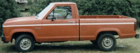
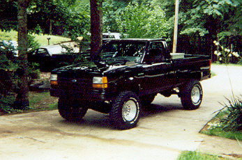
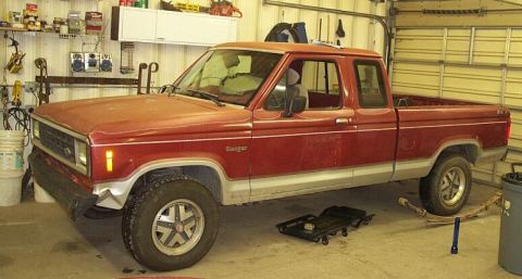
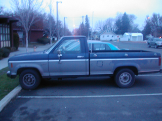
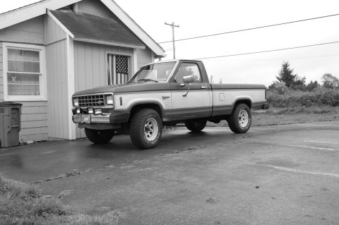
1986 Ford Ranger/
Photo
supermotors.net/registry/media/820398
Ford TFI Module / ICM Connector Pinout Diagram - PIP, SPOUT, TACH Terminals

Reference · 1983-1992 RangerAll 3 manual pages
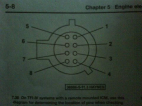
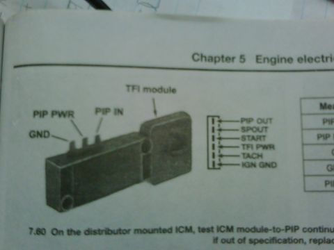
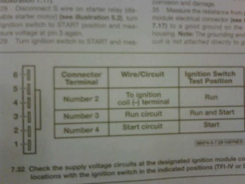
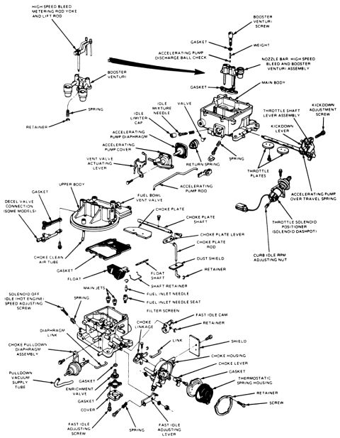
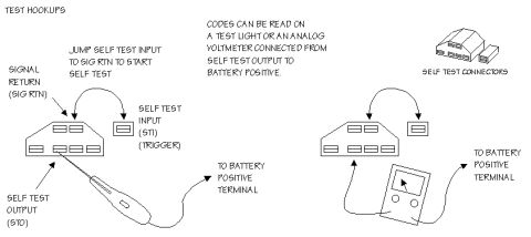
Service manual page showing the TFI ignition module with labeled terminals such as PIP PWR, PIP IN, GND and PIP OUT.
Part of 1983-1992 Ford Ranger Manual Pages
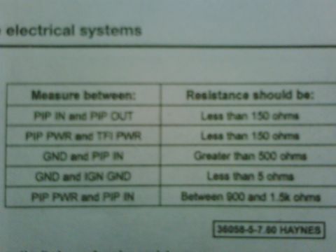
This is a scanned page from Chapter 5 ("Engine electrical") of an automotive repair manual (Haynes-style layout). The page contains figure 7.60, an illustration of a distributor-mounted TFI (Thick Film Ignition) module, also referred to as the ICM (Ignition Control Module). The drawing labels the module's terminals on one side as GND, PIP PWR, and PIP IN, and shows the six-pin harness connector pinout on the other side: PIP OUT, SPOUT, START, TFI PWR, TACH, and IGN GND. A specification table appears at the right edge of the scan but is mostly cut off, showing only partial column/row labels (Mea..., PIP..., G..., PI...). The caption instructs the reader to test ICM module-to-PIP continuity on the distributor-mounted ICM and to replace the component if measurements are out of specification, though the caption text is truncated at the right margin. The page is useful for identifying TFI/ICM connector pin functions and terminal locations when diagnosing Ford TFI ignition system problems.
Is this accurate? Sign in to help verify it.
Frequently asked questions
- What are the pins on the TFI module connector?
- The six-pin connector shown includes: PIP OUT, SPOUT, START, TFI PWR, TACH, and IGN GND.
- What terminals are labeled on the side of the TFI module?
- The illustration labels three terminals on the module: GND, PIP PWR, and PIP IN.
- What test does figure 7.60 describe?
- It describes testing ICM module-to-PIP continuity on the distributor-mounted ICM, and replacing the part if it is out of specification.
- What chapter of the manual is this page from?
- Chapter 5, Engine electrical.

No comments yet.