Home/
Registry/
Ford/
Fairlane/
1968-1969/
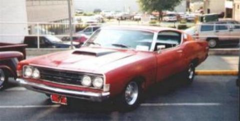
1969 Ford Fairlane/
Photo
supermotors.net/registry/media/1007551
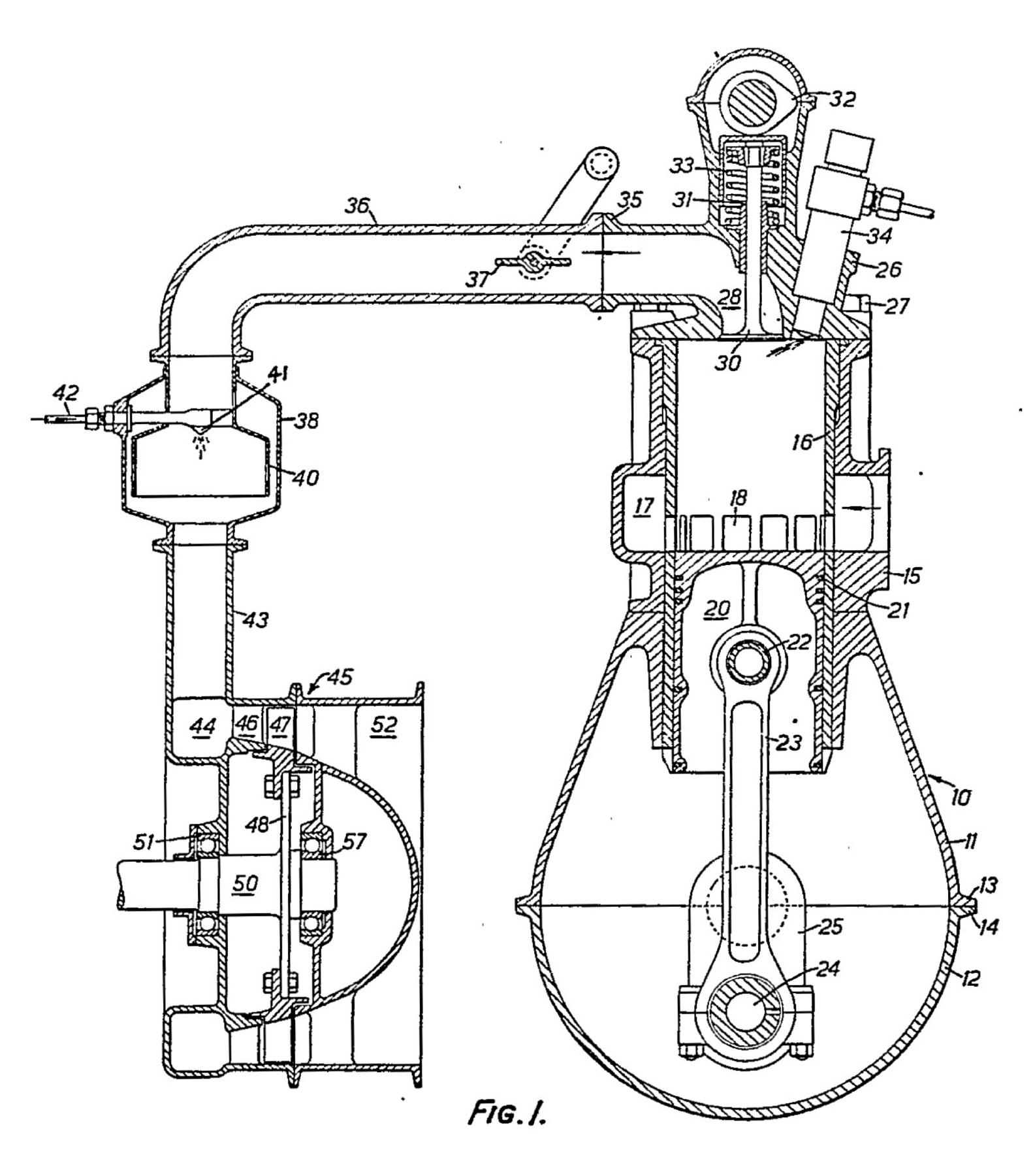
Chatterton Hyperexpansion Engine Patent Drawing Fig. 1 - GB 988378 Schematic
Reference · 1968-1969 FairlaneAll 22 schematics
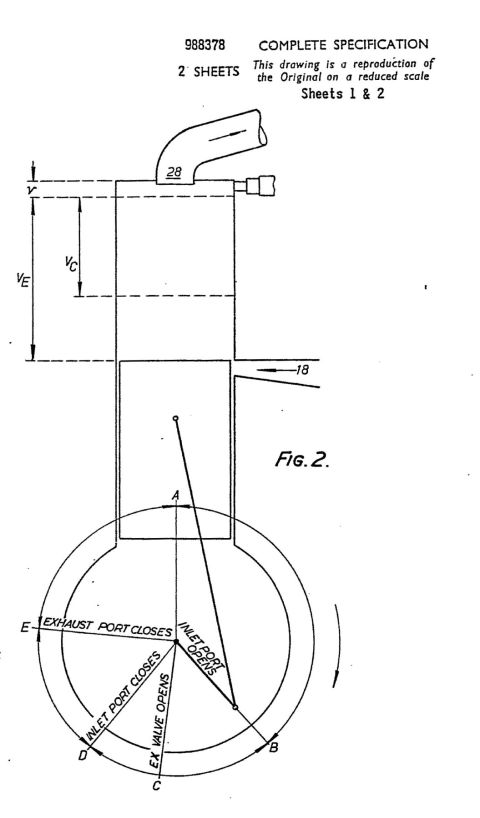
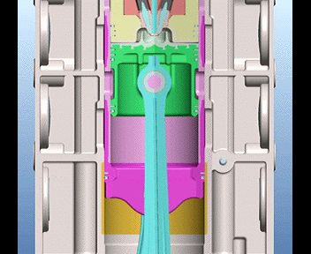

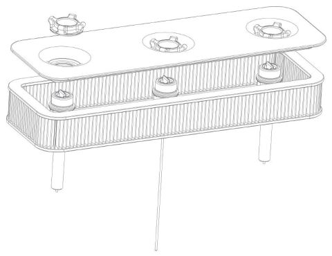
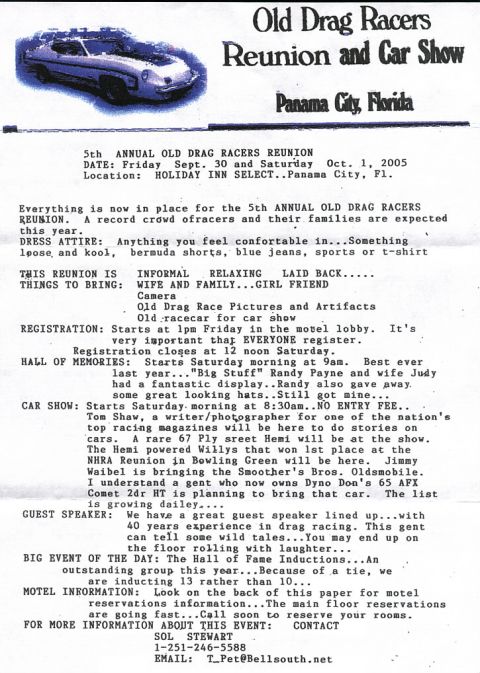
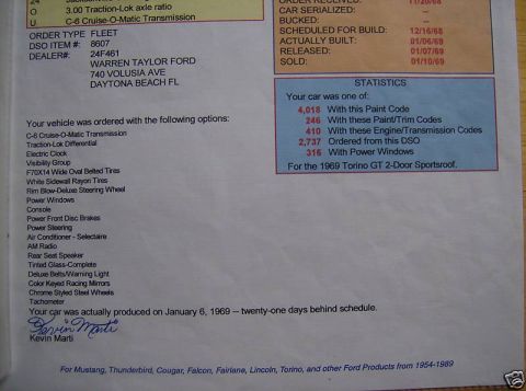
Patent drawing Fig. 1 showing a labeled engine schematic with numbered reference callouts.
Part of 1968-1969 Ford Fairlane Schematics
This document is a single-page patent-style line drawing labeled 'Fig. 1.' It is a sectional (cutaway) schematic of an unconventional internal-combustion engine arrangement. On the right side, a cylinder assembly is shown with a piston (with ring grooves), connecting rod, crankshaft big-end, and a spherical/pear-shaped crankcase, along with a poppet valve, valve spring, rocker-type actuation at the top, and what appears to be an injector or spark device angled into the cylinder head. A large transfer duct (items 35-37, including a butterfly-type valve) runs from the cylinder head across the top of the drawing to a separate chamber on the left containing a spray nozzle or injector (items 41-42) and a combustion/expansion chamber (38, 40). A vertical duct (43) leads down to a lower housing containing a shaft, bearings, and disc assembly (items 44-52, 57), apparently a rotary or turbine-like expander unit. The drawing carries only numeric reference callouts (10 through 57) and no descriptive legend, title block, date, or part text. Based on the filename, it belongs to a multi-page set for British patent GB 988378 (Chatterton 'hyperexpansion' engine), but no such identification is printed on this page itself.
Is this accurate? Sign in to help verify it.
Frequently asked questions
- What does this document show?
- It is a sectional patent-style drawing labeled Fig. 1 showing a piston engine cylinder with valve gear and crankcase on one side, connected by a large duct to a separate chamber with a spray nozzle and a lower housing containing a shaft and disc/bearing assembly.
- Does the drawing include a parts legend or written descriptions?
- No. The page contains only numeric reference callouts (10 through 57) and the caption 'Fig. 1.' There is no text legend identifying what each number means.
- What reference numerals appear on the drawing?
- Visible callouts include 10, 11, 12, 13, 14, 15, 16, 17, 18, 20, 21, 22, 23, 24, 25, 26, 27, 28, 30, 31, 32, 33, 34, 35, 36, 37, 38, 40, 41, 42, 43, 44, 45, 46, 47, 48, 50, 51, 52, and 57.
- Is this a wiring or fuse diagram for a 1969 Ford Fairlane?
- No. It is a mechanical cross-section schematic of an engine concept, not an electrical diagram, and nothing on the page ties it to a Ford Fairlane.
No comments yet.