Home/
Registry/
Ford/
Fairlane/
1968-1969/
1969 Ford Fairlane/
Photo
supermotors.net/registry/media/899080
3D CAD Cutaway Render - 4-Cylinder Ported-Liner Engine Crank & Rod Assembly

Reference · 1968-1969 FairlaneAll 22 schematics
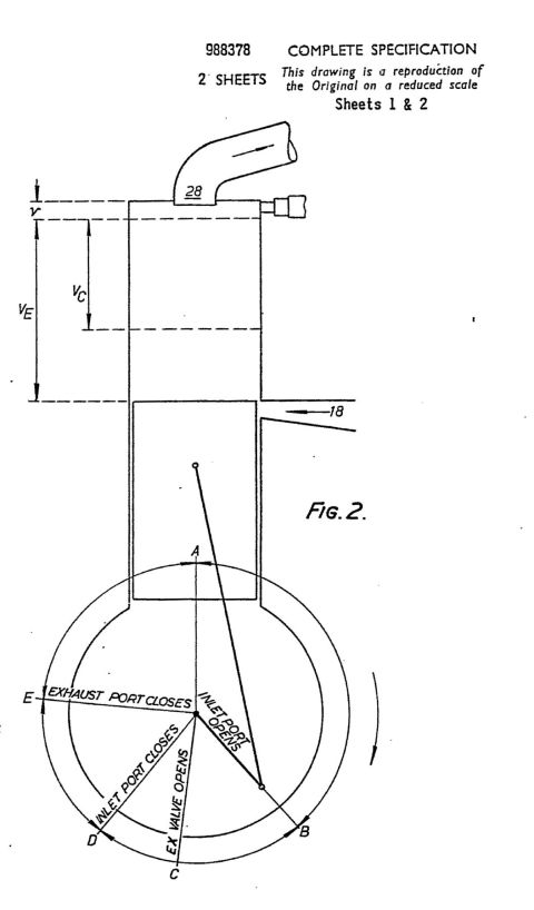
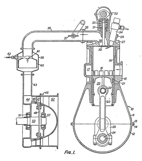
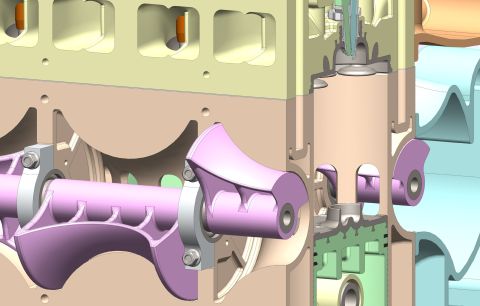
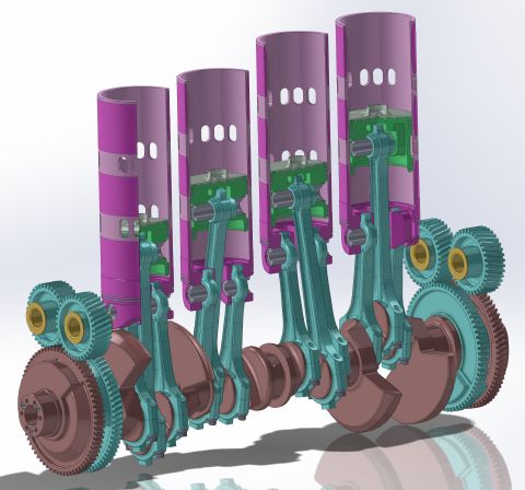
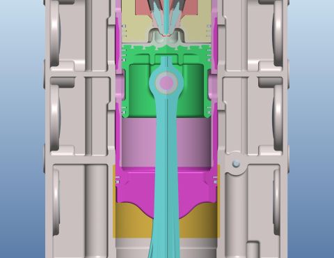
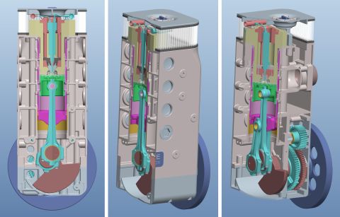
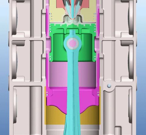

CAD render of the engine crankshaft, connecting-rod, cylinder-liner and gear-drive assembly.
Part of 1968-1969 Ford Fairlane Schematics
This document is not a textual schematic but a full-color 3D CAD rendering (consistent with SolidWorks output) of an internal-combustion engine's rotating and reciprocating assembly, shown in cutaway. It depicts four cylinder liners sectioned lengthwise, each with rows of ports (holes) through the liner walls, suggesting a ported two-stroke or sleeve-type design. Inside each liner is a cutaway piston with visible ring grooves and piston pin. Notably, each crank throw appears to carry paired or articulated connecting rods, with additional short rods linking to secondary pins, an unconventional linkage arrangement. The teal-colored rods connect to a brown crankshaft with large counterweights and a drilled rear flange. At both ends of the crankshaft are gear trains: large crank gears meshing with smaller idler gears fitted with yellow/brass bushings, presumably for camshaft or accessory drive. A reader can learn the general architecture and component relationships of this engine concept, liner porting, piston/rod geometry, crankshaft counterweighting, and gear drive layout, but no textual data (dimensions, part numbers, torque specs, or application years) is provided. The file is part of an album of engine concept figures (IPC engine figures and Chatterton patent pages), and it does not identify any specific production vehicle.
Is this accurate? Sign in to help verify it.
Frequently asked questions
- What does this image show?
- A 3D CAD cutaway rendering of a four-cylinder engine bottom end: sectioned cylinder liners with wall ports, cutaway pistons, connecting rods, a counterweighted crankshaft, and gear trains at both ends.
- Does the image include any part numbers, dimensions, or specifications?
- No. The rendering contains no text, labels, dimensions, torque values, or part numbers of any kind.
- How are the connecting rods arranged?
- Each crank throw appears to carry paired rods, with additional shorter link rods connecting to secondary pins, an unconventional multi-rod linkage rather than a single rod per piston.
- Why do the cylinder liners have holes in them?
- The sectioned liners show multiple rows of oval ports through their walls, indicating a ported-liner design (such as used in two-stroke or sleeve-valve-type engine concepts).
- Does this document identify a specific vehicle or model year?
- No. Nothing in the image identifies a make, model, or year; it is a generic engine concept rendering.
No comments yet.