Home/
Registry/
Ford/
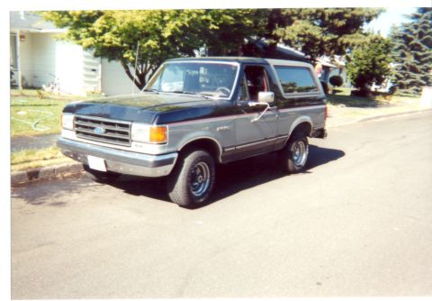
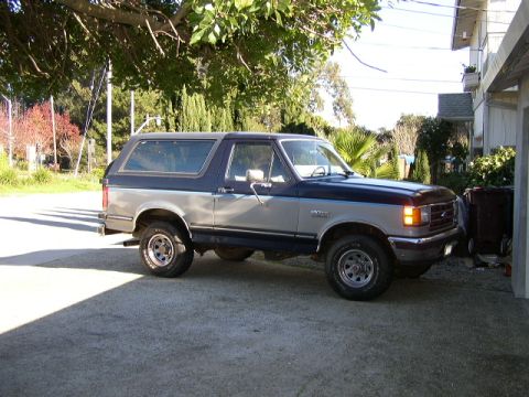
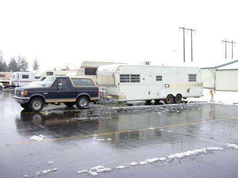
Bronco/
1987-1991/
“Eddie Bauer”/
Photo
supermotors.net/registry/media/1046697
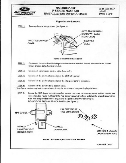
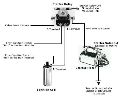
Document shows installation instructions for Ford F-Series Mass Air system, including diagrams of throttle linkage and MAP sensor.
MOTORSPORT 13-M-9000-T51 F-SERIES MASS AIR 1/21/93 Fmi INSTALLATION INSTRUCTIONS PAGE 3 OF 9 Upper Intake Removal STEP l: Remove throttle linkage cover. (See Figure 2). AUTO TRANSMISSION KICKDOWN CABLE (AUTO ONLY) THROTTLE CABLE THROTTLE LINKAGE L ' '- COVER L h _.-"' Tip- I; dig-11"; FIGURE 2. THROTTLE LINKAGE COVER STEP 2: Disconnect the throttle cable linkage from the throttle lever ball. Loosen and remove the thrOttle linkage bracket bolu. Remove bracket STEP 3 Disconnect transmission control cable. (auto only). STEP 4 Disconnect the electrical connector at the EGR valve sensor. STEP 5: Disconnect the electrial connector at the idle speed control connector. STEP 6: Disconnecc the rhmttle body coolant hoses Note: Some coolant may leak from the hoses it may be necessary to temporarily plug the hoses. STEP 7: Locate the MAP Sensor to intake manifold vacuum tree hose. cut the map sensor molded vacuum tree connector.(See Figure 3). Discard the Map Sensor vacuum tree hose and plug the unused vacuum tree tube with the provided rubber plug. Leave the port on the MAP sensor open. DO NOT CAP THE MAP SENSOR FOR ll! (See Figure 3}. MOLDED VACUUM | MAP SENSOR TREE CONNECTOR : | INTAKE _ HARNESS | my 1:? CONNECTOR WWW (MAP SENSOR HOSE) FIGURE 3 MAP SENSOR/MOLDED VACUUM ASSEMBLY *EXAMPLE ONLY
Comments
More from this build


No comments yet.