Home/
Registry/
Ford/
Bronco/
1987-1991/
“Eddie Bauer”/
Photo
supermotors.net/registry/media/1046698
Ford Motorsport F-Series Mass Air Install Instructions Page 4 - EGR & Vacuum
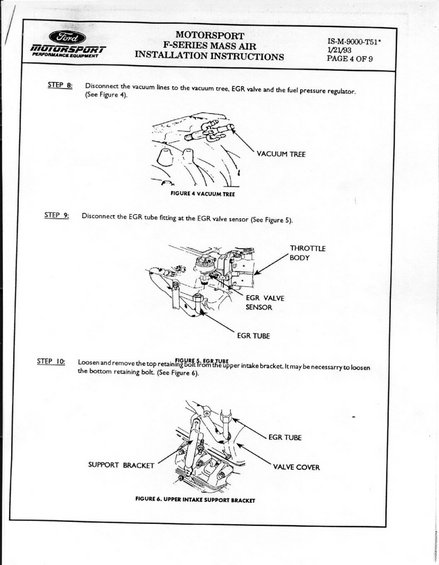
Page 4 of the Ford Motorsport Mass Air install: disconnecting vacuum-tree lines to EGR valve and fuel pressure regulator, removing the EGR tube fitting and upper intake support bracket bolts.
This document is page 4 of 9 of the Ford Motorsport (FMS) F-Series Mass Air Installation Instructions, document number IS-M-9000-T51, dated 1/21/93. It covers Steps 8 through 10 of the mass air flow (MAF) conversion procedure. Step 8 instructs the installer to disconnect the vacuum lines to the vacuum tree, EGR valve, and fuel pressure regulator, with Figure 4 illustrating the vacuum tree location on the upper intake. Step 9 covers disconnecting the EGR tube fitting at the EGR valve sensor; Figure 5 shows the throttle body, EGR valve sensor, and EGR tube. Step 10 instructs loosening and removing the top retaining bolt from the upper intake support bracket (noting it may be necessary to loosen the bottom retaining bolt), with Figure 6 depicting the upper intake support bracket, EGR tube, and valve cover. A reader learns the disassembly sequence for vacuum lines, EGR plumbing, and intake bracketry needed during the speed-density-to-mass-air conversion on Ford F-Series EFI engines. No torque values, part numbers for components, or wiring details appear on this page.
Is this accurate? Sign in to help verify it.
Frequently asked questions
- What does Step 8 of the Ford Motorsport Mass Air installation cover?
- Disconnecting the vacuum lines to the vacuum tree, EGR valve, and the fuel pressure regulator, as shown in Figure 4.
- Where is the EGR tube disconnected during the mass air conversion?
- Step 9 says to disconnect the EGR tube fitting at the EGR valve sensor, shown in Figure 5 near the throttle body.
- What is removed from the upper intake support bracket in Step 10?
- The top retaining bolt is loosened and removed from the upper intake bracket; it may also be necessary to loosen the bottom retaining bolt (Figure 6).
- What is the document number and date of these instructions?
- IS-M-9000-T51, dated 1/21/93, page 4 of 9.
Comments
More from this build














No comments yet.