Home/
Registry/
Ford/
Model T/
1908-1927/
“Centennial”/
Photo
supermotors.net/registry/media/1051118
Vintage 6-Volt Generator Cut-Out & Ammeter Charging Circuit Diagram (Fig. 4)
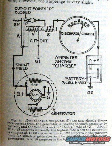
Charging system wiring diagram showing the generator, cut-out points, shunt field, ammeter on charge, and 6-volt battery.
Part of 1908-1927 Ford Model T Wiring Diagrams
This is a scanned page from a vintage automotive reference book showing Fig. 4, a schematic wiring diagram of a generator charging circuit with the cut-out points (P) closed. The diagram illustrates a shunt-field generator (with commutator "COM.", B+ and -G terminals, and shunt field windings labeled SHF) connected through a cut-out relay (with series winding S, voltage winding V, contact points P, spring SP, and armature A, grounded at G1) to an ammeter and a 3-cell 6-volt battery (grounded at G2). The ammeter face reads "DISCHARGE / CHARGE" with a 30-0-30 scale, and the caption notes the needle shows "charge" because current from the generator is flowing through the ammeter to the battery. The caption explains that 10 to 15 amperes is usually the highest charging rate when the generator runs at 1,000 rpm or more, that 22 amperes is the extreme limit to which a generator can be adjusted, and that some generators are limited to 15 or 16 amperes. A reader learns how the cut-out connects the generator to the battery, how charging current registers on the ammeter, and typical/maximum generator charging rates for early 6-volt automotive electrical systems.
Is this accurate? Sign in to help verify it.
Frequently asked questions
- What does the ammeter show when the cut-out points (P) are closed?
- When the cut-out points (P) are closed, current from the generator passes through the ammeter to the battery, and the needle registers on the "charge" side of (O).
- What is the normal maximum charging rate of the generator?
- About 10 to 15 amperes is usually the highest rate when the generator is running at 1,000 r.p.m. or more.
- What is the extreme adjustment limit for generator output?
- 22 amperes is the extreme limit for which a generator can be adjusted, and with some generators 15 or 16 amperes is the limit.
- What battery is shown in the diagram?
- A 3-cell, 6-volt battery, grounded at G2, connected through the ammeter to the cut-out and generator.
- What components make up the cut-out in the diagram?
- The cut-out includes contact points "P", a spring (SP.), an armature (A), a voltage winding (V), a series winding (S), a core (C), and a ground connection (G1).
Comments
More from this build



No comments yet.