Ford Model T Ignition Wiring Diagram No. 5 - Coil, Magneto & Commutator Wires
Reference · 1908-1927 Model TAll 3 wiring diagrams
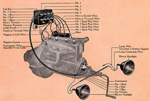
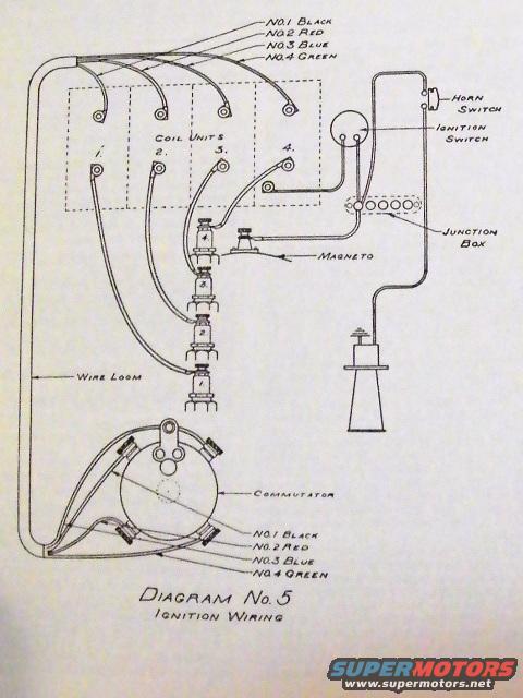
Ignition wiring diagram showing four coil units, magneto, commutator, junction box, and color-coded numbered wires.
Part of 1908-1927 Ford Model T Wiring Diagrams
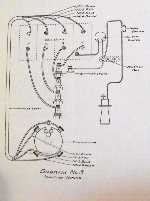
This document is a scanned wiring diagram labeled "Diagram No. 5: Ignition Wiring," apparently from a period Ford Model T reference book. It illustrates the ignition circuit, showing how four numbered wires, No.1 Black, No.2 Red, No.3 Blue, and No.4 Green: run from the four vibrator coil units (numbered 1 through 4) through the wire loom to the commutator (timer) mounted on the engine. The same color code is repeated at both the coil box end and the commutator end of the loom, allowing correct matching of each coil to its corresponding commutator terminal. The diagram also depicts the magneto connection feeding the coil box, the ignition switch and horn switch on the switch panel, and a junction box with multiple terminals where circuits are joined. A component resembling the magneto/horn assembly is drawn at lower right of the switch wiring. Readers can learn the correct wire color assignments for the four ignition coils, the routing of the ignition wiring through the loom, and how the magneto, ignition switch, junction box, and commutator interconnect on this ignition system. The diagram is undated on the page itself; the uploader's filename suggests it covers 1919-1926 wiring.
Is this accurate? Sign in to help verify it.
Frequently asked questions
- What are the wire color codes for the four ignition coils in this diagram?
- No.1 is Black, No.2 is Red, No.3 is Blue, and No.4 is Green. The same color code applies at both the coil unit end and the commutator end of the wire loom.
- What components are shown in Diagram No. 5?
- The diagram shows the four coil units, magneto connection, ignition switch, horn switch, junction box, wire loom, and the commutator.
- How do the coil wires reach the commutator?
- The four color-coded wires (black, red, blue, green) from coil units 1-4 run through the wire loom down to the four terminals on the commutator.
- Where does the magneto connect in this ignition wiring?
- The magneto lead is shown connecting into the coil box/switch circuit near the coil units, with the ignition switch and junction box completing the circuit.
No comments yet.