This document details engine valve clearance adjustments and related procedures.
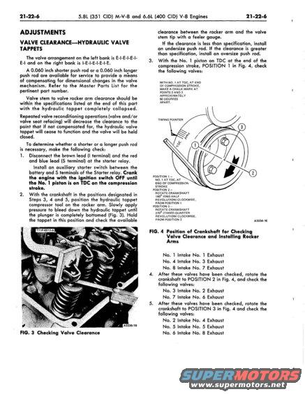
21-22-6 5.8L (351 CID) M-V-8 and 6.6L (400 CID) V~8 Engines 21 -22-6 ADJUSTMENTS VALVE CLEARANCEHYDRAU I.IC VALVE TAPPETS The valve arrangement on the left bank is Esl-E-l-E-l- E-l and on the right bank is I-E-I-E-I-E-l-E. A 0.060 inch shorter push rod or a 0.060 inch longer push rod are available for service to provide a mieans of compensating for dimensional changes in the valve mechanism. Refer to the Master Parts List for the pertinent part number. Valve stem to valve rocker arm clearance should be within the specifications listed at the end of this part with the hydraulic tappet completely collapsed. Repeated valve reconditioning operations (valve and/or valve seat refacing) will decrease the clearance to the point that if not compensated for, the hydraulic valve tappet will cease to function and the valve will be held closed. To determine whether a shorter or a longer push rod is necessary, make the following check: I. Disconnect the brown lead (I terminal) and the red and blue lead (5 terminal) at the starter relay. Install an auxiliary starter switch between the battery and 5 terminals of the Starter relay. Crank the engine with the ignition switch OFF until the No. 1 piston is on TDC on the compression stroke. 2. With the crankshaft in the positions designated in Steps 3, 4 and 5, position the hydraulic tappet compressor tool on the rocker arm. Slowly apply pressure to bleed down the hydraulic tappet until the plunger is completely bottomed (Fig. 3). Hold the tappet in this position and check the available a! m m 2 FIG. 3 Checking Valve Clearance ." A3235-IB clearance between the rocker arm and the valve stem tip with a feeler gauge. If the clearance is less than specification, install an undersize push rod. If the clearance is greater than specification, install an oversize push rod. 3. With the No. I piston on TDC at the end of the compression stroke, POSITION 'I in Fig. 4,. check the following valves: WITH NO. I AT TDC, AT END OF COMPRESSION STROKE, MAKE A CHALK MARK AT POINTS 2 AND It APPROXIMATELY 90 DEGREES APART. TIMING POINTER POSITION I ~ No.1 AT TDC, AT END OF COMPRESSION STROKE POSITION z ROTATE CRANKSHAFT iao" IONE-HALF REVOLUTION) CLOCKWISE. FROM POSITION I POSITION 3 , ROTATE CRANKSHAFT 270 (THREE-QUARTER REVOLUTION) CLOCKWISE, FROM POSITION 2 Aeneas FIG. 4 Position of Crankshaft for Checking Xalve Clearance and Installing Rocker rms No. I Intake No. I Exhaust No. 4 Intake No. 3 Exhaust No. 8 Intake No. 7 Exhaust 4. After these valves have been checked, rotate the crankshaft to POSITION 2 in Fig. 4, and check the following valves: No. 3 Intake No. 2 Exhaust No. 7 Intake No. 6 Exhaust 5. After these valves have been checked, rotate the crankshaft to POSITION 3 in Fig. 4 and check the following valves: No. 2 Intake No. 4 Exhaust No. 5 Intake Na. 5 Exhaust No. 6 Intake No. 8 Exhaust
Comments
More from this build


No comments yet.