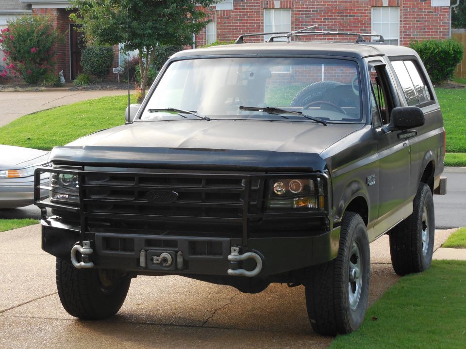
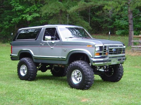
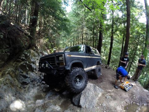
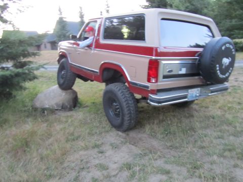
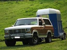
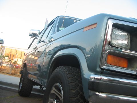
The third-generation Ford Bronco ran from 1980 to 1986 on Ford's redesigned 1980-1986 F-series chassis, the body enthusiasts call the "Bullnose" for its flat, forward-leaning front end and recessed grille. Ford rebodied the full-size Bronco to cut weight and improve fuel economy after the 1979 energy crisis, and the headline chassis change was the Twin-Traction Beam (TTB) front suspension, an independent setup using a Dana 44 front axle split into two swinging beams. The engine roster covered the 300 cubic-inch (4.9L) inline-six and the 302 (5.0L) V8, plus an optional 5.8L V8 that changed identity early in the run: for 1980-1981 it was the 351M, a member of Ford's 335-series ("Cleveland"/M-block) family carried over from the prior generation, replaced by the lighter 351 Windsor for 1982, which then served as the top V8 for the rest of the generation. The early years leaned on smaller, economy-tuned options. Trims spanned the base Custom and the XLT, with the Eddie Bauer package joining for 1985. Around the 1985 model year the 5.0L (302) V8 picked up Ford electronic fuel injection (EFI), while the 5.8L (351 Windsor) stayed carbureted through the end of this generation. All seven model years used the same 104.7-inch wheelbase and removable rear hardtop.
Other Ford Bronco generations
At a glance
- Years: 1980-1986 (third generation, "Bullnose")
- Body: two-door full-size SUV on the 1980-1986 F-series chassis, removable fiberglass rear hardtop
- Engines: 300 cu in (4.9L) inline-six; 302 (5.0L) V8; optional 5.8L V8 (351M (335-series) for 1980-1981, replaced by the 351 Windsor for 1982)
- Front suspension: Twin-Traction Beam (TTB) independent, Dana 44 front axle
- Rear axle: Ford 9-inch semi-floating live axle, leaf-sprung (Ford 8.8-inch phased in toward the end of the generation, about 1986, and standard for 1987)
- Transmissions: 4-speed manual and 3-speed automatic; transfer case for four-wheel drive
- Trims: Custom, XLT; Eddie Bauer from 1985
- Wheelbase: 104.7 inches (all years)
Year-by-year changes
| Year | Engines | Drivetrain & suspension | Notable changes |
|---|---|---|---|
| 1980 | 300 cu in (4.9L) six; 302 (5.0L) V8 (returns as base V8); optional 351M (335-series) (5.8L) V8 | New Twin-Traction Beam independent front suspension with Dana 44 axle; rear leaf-sprung live axle | Full redesign onto the Bullnose F-series body; lighter structure aimed at fuel economy after the 1979 fuel crisis; 400 V8 dropped after 1979, optional big V8 is the carried-over 351M |
| 1981 | 300 six; 302 V8; optional 351M (335-series) (5.8L) V8 | TTB front, Dana 44 front axle; 4-speed manual or automatic | Carryover year refining the 1980 redesign, continued economy focus; optional big V8 still the 351M |
| 1982 | 300 six; 302 V8; 351 (5.8L) Windsor V8 (replacing the 351M) | TTB front; four-wheel-drive transfer case | Optional 5.8L switches from the discontinued 351M (335-series) to the lighter 351 Windsor, which becomes the top engine option for the rest of the generation; revised Ford front-end styling and the Blue Oval grille emblem era |
| 1983 | 300 six; 302 V8; 351 (5.8L) Windsor V8 | TTB front, Dana 44; manual and automatic transmissions | Mid-generation engine availability; a 351 High Output (HO) version of the 5.8L Windsor appeared around the mid-1980s |
| 1984 | 300 six; 302 V8; 351 V8 | TTB front; four-wheel drive | Carryover year; the separate compact Bronco II launched alongside but is a different Ranger-based model, not this full-size Bronco |
| 1985 | 300 six; 302 (5.0L) V8 with electronic fuel injection (EFI); 351 (5.8L) carbureted V8 | TTB front, Dana 44; automatic and manual options | Eddie Bauer trim package introduced; the 5.0L V8 adopted Ford electronic fuel injection (EFI) while the 5.8L stayed carbureted |
| 1986 | 300 six; 302 (5.0L) V8 with electronic fuel injection (EFI); 351 (5.8L) carbureted V8 | TTB front; four-wheel-drive transfer case | Final year of the Bullnose body before the 1987 Bricknose redesign; the 5.0L V8 ran EFI, the 5.8L remained carbureted; Ford began phasing in the lighter Ford 8.8-inch rear axle around 1986, which became standard for 1987 |
Engines and drivetrain
The third-generation Bronco (1980-1986) offered three engine families across its run. The base engine was the 300 cubic-inch (4.9L) Ford inline-six, a long-stroke, torque-oriented motor known for durability rather than power. Above it sat the 302 (5.0L) Windsor V8 and an optional 5.8L V8 whose identity changed early in the run. For 1980-1981 the optional 5.8L was the 351M, a member of Ford's 335-series ("Cleveland"/M-block) family carried over from the prior generation; the 400 V8 was dropped after 1979 and the 302 returned as the base V8 for 1980. The 335-series 351M was discontinued around 1982, with the Bronco and F-series among its last homes, and the lighter 351 Windsor (5.8L) replaced it for 1982, continuing as the top V8 for the rest of the generation. Ford tuned the early 1980-1981 trucks for fuel economy in the wake of the 1979 energy crisis. Around the mid-1980s Ford offered a 351 High Output (HO) version of the 5.8L Windsor. Around the 1985 model year the 5.0L (302) gained Ford electronic fuel injection (EFI), the same direction the F-series trucks were heading, while the 5.8L (351 Windsor) stayed carbureted through the end of this generation and did not get EFI until the following 1987-1991 trucks. Transmissions were 4-speed manuals and 3-speed automatics depending on engine and year, feeding a transfer case for four-wheel drive.
What is Twin-Traction Beam, and why does it matter?
Twin-Traction Beam (TTB) was the defining chassis change of the 1980-1986 Bronco. Earlier full-size Broncos (1978-1979) used a solid front axle on leaf springs; for the 1980 redesign Ford split the front Dana 44 into two long swinging beams, each pivoting independently, with coil springs and radius arms. The result is an independent-front-suspension feel that improves on-road ride and handling compared with a solid axle, while still using axle-style hardware. TTB comes with tradeoffs that enthusiasts still debate: it rides better than a solid axle but complicates lift kits and alignment because camber changes as each beam travels. The system carried forward into later Ford trucks, so the 1980-1986 Bronco is where this distinctive Ford geometry first appeared under the full-size Bronco.
Axles, suspension, and four-wheel drive
The 1980-1986 Bronco used a Dana 44 front axle within the Twin-Traction Beam layout, with coil springs and radius arms locating the front beams. The rear was a Ford 9-inch semi-floating live axle on leaf springs for most of the generation, though around 1986 Ford began phasing in the smaller, lighter Ford 8.8-inch rear axle across its half-ton trucks, and the 8.8-inch became the standard rear axle for the following 1987 generation. Four-wheel drive was handled through a transfer case, with manual locking front hubs typical of the era. Because the front is independent rather than a single solid tube, the third-generation Bronco behaves differently off-road and on the lift-kit market than the solid-axle first- and second-generation trucks. Buyers cross-shopping vintage Broncos should know that the 1980-1986 TTB front end is the dividing line between the older solid-axle full-size Broncos (1978-1979) and this redesigned chassis.
Body, trims, and identifying the Bullnose
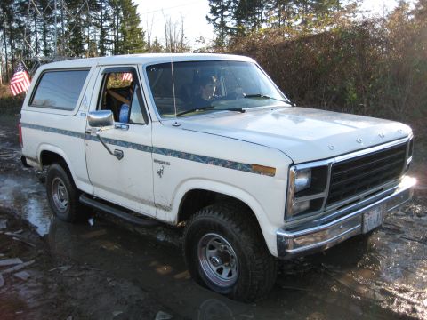
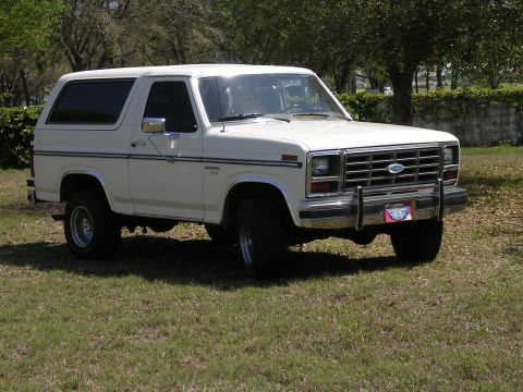
The third-generation Bronco (1980-1986) shares its cab and front sheet metal with the 1980-1986 F-series pickups, the styling generation enthusiasts call "Bullnose" for its flat, slightly forward-leaning nose and recessed grille. It remained a two-door full-size SUV with a removable fiberglass rear hardtop over the cargo area and a single 104.7-inch wheelbase. Trim levels ran from the base Custom up through XLT, and Ford added the Eddie Bauer package for 1985, bringing two-tone paint and upgraded interior trim. Do not confuse this truck with the compact Bronco II that launched for 1984: the Bronco II is a separate, smaller model built on the Ranger platform with a V6, not a full-size Bronco.
What to know when buying a 1980-1986 Bronco
Shoppers looking at a third-generation Bronco (1980-1986) should verify the engine, since the 300 six, 302, and 351 differ greatly in power, and confirm whether a 5.0L example is carbureted or one of the later fuel-injected (EFI) trucks, since the 5.8L stayed carbureted throughout, which affects parts and tuning. The Twin-Traction Beam front end is the key inspection item: check for worn radius-arm bushings, ball joints, and the camber/alignment behavior that TTB introduces, and be aware that lift kits for TTB trucks differ from solid-axle kits. As with most full-size Fords of the era, body and frame rust around the rear quarters, rockers, and tailgate is the common structural concern. The removable hardtop and its seals are worth checking for leaks and corrosion.
Frequently asked questions
What years is the third-generation Ford Bronco?
The third-generation Ford Bronco was built from 1980 to 1986. It rode on Ford's redesigned 1980-1986 F-series chassis, the body enthusiasts call "Bullnose," and it replaced the 1978-1979 second-generation "Dentside" Bronco. It was succeeded by the 1987-1991 fourth-generation "Bricknose" Bronco.
What is the Twin-Traction Beam front suspension on the 1980-1986 Bronco?
Twin-Traction Beam (TTB) is the independent front suspension Ford introduced on the 1980 Bronco. It splits a Dana 44 front axle into two long swinging beams that pivot independently, sprung by coils and located by radius arms. It improves on-road ride over a solid axle but changes camber through suspension travel, which complicates alignment and lift kits.
What engines did the third-generation Bronco use?
The 1980-1986 Bronco offered the 300 cubic-inch (4.9L) inline-six as the base engine, plus the 302 (5.0L) V8 and an optional 5.8L V8. For 1980-1981 the optional 5.8L was the 351M (335-series), carried over from the prior generation; it was replaced by the lighter 351 Windsor (5.8L) for 1982, which served as the top V8 for the rest of the run. A 351 High Output version of the Windsor appeared around the mid-1980s, and around the 1985 model year the 5.0L V8 adopted Ford electronic fuel injection (EFI) while the 5.8L stayed carbureted through this generation.
Is the Bronco II the same as the 1980-1986 Bronco?
No. The Bronco II (1984-1990) is a separate compact SUV built on the Ford Ranger platform with a Cologne V6, not the full-size Bronco. The third-generation full-size Bronco (1980-1986) is a larger, two-door truck sharing its body with the F-series pickups.
What is the difference between the Bullnose Bronco and the earlier full-size Broncos?
The 1980-1986 "Bullnose" Bronco uses a redesigned, lighter F-series body and a Twin-Traction Beam independent front suspension. The earlier 1978-1979 "Dentside" full-size Bronco used a solid front axle on leaf springs. The TTB front end is the clearest mechanical dividing line between the two.
Sources
- Ford factory shop manuals and parts catalogs for the 1980-1986 F-series and Bronco
- VIN and door data-plate decoding for engine, axle, and trim verification
- Established full-size Bronco reference works, registries, and owner community documentation
- Period road tests and Ford sales literature of the 1980-1986 model years
Asked all the time
What years is the third-generation Ford Bronco?
The third-generation Ford Bronco was built from 1980 to 1986. It rode on Ford's redesigned 1980-1986 F-series chassis, the body enthusiasts call "Bullnose," and it replaced the 1978-1979 second-generation "Dentside" Bronco. It was succeeded by the 1987-1991 fourth-generation "Bricknose" Bronco.
What is the Twin-Traction Beam front suspension on the 1980-1986 Bronco?
Twin-Traction Beam (TTB) is the independent front suspension Ford introduced on the 1980 Bronco. It splits a Dana 44 front axle into two long swinging beams that pivot independently, sprung by coils and located by radius arms. It improves on-road ride over a solid axle but changes camber through suspension travel, which complicates alignment and lift kits.
What engines did the third-generation Bronco use?
The 1980-1986 Bronco offered the 300 cubic-inch (4.9L) inline-six as the base engine, plus the 302 (5.0L) V8 and an optional 5.8L V8. For 1980-1981 the optional 5.8L was the 351M (335-series), carried over from the prior generation; it was replaced by the lighter 351 Windsor (5.8L) for 1982, which served as the top V8 for the rest of the run. A 351 High Output version of the Windsor appeared around the mid-1980s, and around the 1985 model year the 5.0L V8 adopted Ford electronic fuel injection (EFI) while the 5.8L stayed carbureted through this generation.
Is the Bronco II the same as the 1980-1986 Bronco?
No. The Bronco II (1984-1990) is a separate compact SUV built on the Ford Ranger platform with a Cologne V6, not the full-size Bronco. The third-generation full-size Bronco (1980-1986) is a larger, two-door truck sharing its body with the F-series pickups.
What is the difference between the Bullnose Bronco and the earlier full-size Broncos?
The 1980-1986 "Bullnose" Bronco uses a redesigned, lighter F-series body and a Twin-Traction Beam independent front suspension. The earlier 1978-1979 "Dentside" full-size Bronco used a solid front axle on leaf springs. The TTB front end is the clearest mechanical dividing line between the two.
Technical Reference
Member-uploaded diagrams & documents for this generation. AI-classified; community-verified where badged.
Wiring Diagrams (56)
- 1996 Ford Bronco & F-Series Trailer Wiring Diagram - 7-Pin Connector PinoutThis document is a factory-style trailer adapter wiring diagram for the 1996 Ford Bronco and F-Series trucks. It maps the complete trailer towing electrical system, including the trailer marker lamps relay, trailer…
- 1994 & 1996 Ford F-Series/Bronco Trailer Camper Wiring Diagram - Tow PackageThis document is a two-page Ford factory-style wiring diagram covering Trailer/Camper Wiring for 1994 (left page) and 1996 (right page) full-size Ford trucks (F-Series and Bronco, with notes such as 'F-SERIES ONLY' and…
- Ford 4WABS Bypass for PSOM - ABS Module Connector C119 Wiring DiagramThis document is a hand-annotated wiring diagram titled "4WABS Bypass for PSOM," showing the connector face of the Ford Anti-Lock Brake Electronic Control Module (part designation 12A581), gray connector C119. Every…
- 1992-1996 Ford Bronco Tailgate Wiring Harness Routing DiagramThis document is an illustrated diagram titled "'92-96 Bronco Tailgate Wiring Harness," showing the routing and mounting of the tailgate wiring harness on 1992-1996 Ford Broncos. The left illustration shows the harness…
- Ford Bronco Master Dash Tailgate Window Switch Wiring - C274 Connector PinoutThis document is a connector pinout diagram for the master (dash-mounted) tailgate window switch, identified as connector C274 (gray). It shows a graphical representation of the 5-pin switch connector with the wire…
- Ford Bronco Tailgate Window Wiring Diagram - Circuit, Connectors & Wire ColorsThis document is a wiring diagram for the Ford Bronco tailgate power window circuit. It traces power from the fuse panel (fuse 12, a 20A circuit breaker, hot at all times) and from the power windows circuit (hot in ACC…
- 1992-96 Ford 4.9L Battery & Starter Cable Routing Diagram (Bronco/F-Series)This document is an exploded/illustrated parts diagram showing the battery and starter wiring arrangement for 1992-1996 Ford trucks equipped with the 4.9L engine. The main illustration depicts the battery, battery…
- 1992-96 Ford Bronco Fuel Pump Wiring Diagram - Relay, Inertia Switch, EECThis is a wiring diagram for the fuel pump circuit on 1992-1996 Ford Broncos. It shows power distribution from the engine compartment fuse box: fuse U (20A, hot in start or run) and fuses I and O (20A each, hot at all…
- 1992-Up Ford Multifunction Switch (MFS) Testing - Terminal Pinout & Ohm ValuesThis document is a testing reference for the 1992-and-up Ford multifunction switch (MFS), the steering-column-mounted switch controlling turn signals, hazard flashers, headlight dimmer/flash-to-pass, and windshield…
- 1996 Ford F-Series/Bronco EEC/PCM Connector Pinout Diagram: 4.9L 5.0L 5.8LThis document is a wiring/connector reference diagram titled "'96 F-Series/Bronco EEC/PCM Connectors," covering the 4.9L inline six, 5.0L V8, and 5.8L V8 engines in 1996 Ford F-Series trucks and Broncos. For each…
- 1995 Ford Bronco BOO Brake Switch & Turn Signal Wiring Diagram (Stop Lamps)This is a color-coded wiring diagram titled "'95 Bronco BOO" covering the Brake On/Off (BOO) switch, turn signal, hazard, and stop lamp circuits on a 1995 Ford Bronco. Power originates from two 15A fuses in the fuse…
- Ford C913 Connector Pinout - Automatic Day/Night Mirror Wiring DiagramThis document is a connector pinout diagram for Ford connector C913 (a black connector) serving the Automatic Day/Night Mirror. It shows a 3-pin connector drawn face-on with pins numbered 1, 2, and 3 from left to…
- 1994-1996 Ford Bronco/F-150 Airbag Circuit Wiring Diagram - SRS Sensors & PinsThis document is a wiring diagram titled "'94-96 Airbag Circuit," covering the supplemental restraint (air bag) system for 1994-1996 Ford trucks. It shows the Air Bag Diagnostic Monitor with its pin assignments and…
- Ford Bronco 4WABS Anti-Lock Brake Wiring Diagram - Connector Pinouts C119 C121This document is a detailed wiring diagram for the Ford 4WABS (four-wheel anti-lock brake system). It maps the complete circuit from power sources (fuse panel fuse 17 10A and fuse 13 15A, plus engine compartment fuse…
- 1992-96 Ford F-Series Power Window Wiring Diagram (& '97 >8500 GVWR)This is a hand-annotated wiring diagram for the power window system on 1992-96 Ford F-series trucks (and 1997 models over 8500 GVWR), explicitly excluding Crew Cab models. Power originates at fuse panel position 14, a…
- 1995 Ford Bronco/F-Series Instrument Cluster Pinout - C250 & C251 ConnectorsThis document is a pinout reference for the 1995 ("'95") instrument cluster connectors, showing the two connectors on the back of the gauge cluster: C250 (black) and C251 (gray). Each connector is illustrated with its…
- 1994-1997 Ford Shift Lock Actuator Wiring Diagram - BOO Switch & Circuit 511This document is a wiring diagram for the shift lock (brake-shift interlock) system on 1994-1997 Ford trucks, drawn/annotated by Steve83. It shows two power feeds from the fuse panel: fuse 18 (10A, hot in run)…
- 1985 Ford Bronco Ignition & Starter Relay Wiring Diagram - Battery to IgnitionThis is a simple hand-drawn (computer-drafted) wiring diagram, uploaded as "Ignition Diagram.jpg" for a 1985 Ford Bronco, showing a two-relay starting and ignition circuit. It depicts a BATTERY with its negative…
- Ford Bronco Ignition Relay Wiring Diagram - Battery to Ignition SwitchThis is a simple hand-drawn wiring diagram (drawn in a computer drawing program) uploaded to illustrate an ignition relay setup, filed under a 1985 Ford Bronco. The diagram shows four labeled elements: a battery (with…
- Ford Diesel Dual Fuel Tank Gauge & Selector Valve Wiring DiagramThis document is a wiring diagram titled 'Diesel Fuel Gauge' showing the dual fuel tank gauge and tank-selection circuit for a Ford diesel truck. Power comes from two fuse panel circuits, a 15A fuse (hot in ACC or RUN)…
- 1995 Ford Bronco Charging System Wiring Diagram - Alternator & RegulatorThis is page 12-1, "Charging System," from the 1995 Ford Bronco electrical/vacuum troubleshooting manual (EVTM). It presents the complete charging system wiring diagram, showing the battery, generator/voltage regulator…
- Ford Duraspark Ignition Wiring Diagram - Module D9VZ-12A199-AX Wire ColorsThis document is a wiring schematic for a Ford Duraspark ignition system. It shows how the ignition switch (with S, R, and S terminals) connects through a wiring kit (part number D9VZ-12A199-AK) to the ignition coil…
- Ford Duraspark Ignition Module Wiring Diagram - 1982 Bronco Wire ColorsThis document is a schematic wiring diagram for a Ford Duraspark-style breakerless ignition system, showing the ignition module, distributor, ignition coil, ballast resistor, ignition switch, and battery. The ignition…
- 1981 Ford F-Series/Bronco Wiring Diagram Part 1 - Fuse Box & Wire ColorsThis document is page 12-19 from Chapter 12 (Chassis electrical system) of a repair manual, showing Part 1 of the full-chassis wiring diagram for the 1981 Ford F-Series Pick-up. The diagram traces circuits and wire…
- 1981 Ford F-Series Wiring Diagram Part 1 - Fuse Box, Lights & Ignition CircuitsThis document is a scanned page (12-19) from Chapter 12, "Chassis electrical system," of an automotive repair manual, showing the wiring diagram titled "1981 F-Series Pick-up - Part 1." The schematic covers the…
- Intake Manifold Heat Strip Wiring Diagram - Temp Switch & Cab Switch CircuitThis is a simple, hand-drawn wiring diagram for an intake manifold heat strip (intake heater) circuit, uploaded to a 1981 Ford Bronco gallery under the filename "Intake heat.jpg." The diagram shows four components: an…
- 1986 Ford Bronco Speed Control (Cruise) Wiring Diagram - Servo & AmplifierThis is a photographed page from a Ford wiring diagram manual (EVTM-style) showing the speed control (cruise control) system schematic, filed by the uploader for a 1986 Ford Bronco. The diagram traces power from a…
- Ford Charging System Wiring Diagram - Electronic Regulator, Warning Light & AmmeterThis is page 171 of a printed automotive service manual showing two charging system wiring diagrams. Figure 5.13 depicts a charging system with an electronic voltage regulator and a warning light indicator (referencing…
- Ford Wiring Diagram - Ignition Switch, Light Switch & Horn Wire ColorsThis document is a close-up photograph of a section of a Ford factory-style wiring diagram, apparently from a printed shop manual or wiring schematic sheet. The visible portion covers the instrument panel and steering…
- Ford Bronco Kill Switch Wiring Diagram - Hella Battery Switch, Starter CircuitThis document is a four-panel wiring diagram set (watermarked "Steve83") showing how to wire a Hella battery kill switch into a vehicle's starter circuit. The first panel, "STOCK STARTER CIRCUIT," shows the factory…
- Dual Horn Wiring Diagram - Air Horns & Stock Horns with Relays & SPDT SwitchThis is a hand-drawn wiring diagram (created in a basic drawing program) showing how to wire dual horn systems, aftermarket air horns and factory stock horns, on one vehicle using two relays and a selector switch. A…
- Ford Bronco Air Horn Compressor Relay Wiring Diagram - Pins 30/85/86/87, 20A FuseThis document is a hand-drawn (computer-sketched) aftermarket horn/air compressor wiring diagram uploaded to a 1986 Ford Bronco gallery. It shows how to wire a new relay to control a compressor (likely for an air horn)…
- 1986 Ford Bronco & F-Series Wiring Diagram Part 1 - Chassis Electrical, FusesThis is page 12-29 from Chapter 12 (Chassis electrical system) of a Haynes-style repair manual, showing Part 1 of the chassis wiring diagram for the 1986 Ford F-Series Pick-up and Bronco. The diagram traces circuits…
- 1987-89 Ford F-Series & Bronco Wiring Diagram - Starting, Charging, WipersThis is page 12-49 from Chapter 12 (Chassis electrical system) of a repair manual, showing chassis wiring diagrams for 1987-89 Ford F-Series trucks and Bronco. The page contains five schematic diagrams. The top-left…
- 1987-91 Ford F-Series & Bronco Chassis Wiring Diagram - Exterior LightsThis is page 12-50 from Chapter 12 (Chassis electrical system) of a Haynes-style repair manual, showing a chassis wiring diagram captioned "Chassis wiring - 1987-91 F-Series and Bronco." The diagram covers exterior…
- 1985 Ford F-Series & Bronco Wiring Diagram - EEC, Lighting, Alternator (Fig 109)This is a scanned page (6-70, Chassis Electrical) from an automotive service manual showing Figure 109, a wiring diagram labeled '1985 F-Series pick-up and Bronco, section two.' The schematic covers the front lighting…
- 1985 Ford F-Series & Bronco Wiring Diagram - Chassis Electrical, Fuse Box (6-69)This is a scanned page (6-69) from a chassis electrical section of an automotive service manual, showing Figure 108: the wiring diagram for the 1985 Ford F-Series pickup and Bronco, section one. The diagram traces…
- Ford Duraspark Ignition Wiring Diagram - D9VZ-12A199-AX Module & Wire KitThis document is a hand-drawn/scanned wiring schematic for a Ford Duraspark-style electronic ignition system, showing how to wire the D5TZ-12A199-AK wire kit between the ignition switch, ignition coil, D5TZ-12127-FX…
- Ford Duraspark Ignition Module Wiring Diagram - Blue Connector ConversionThis document is a hand-drawn/computer-drawn wiring diagram, credited to 'MustangSteve' (http://www.mustangsteve.com) and hosted via WWW.FORD-TRUCKS.COM, showing how to wire a Ford Duraspark ignition module (the…
- Relay Controlled Headlights Wiring Diagram - Ford Bronco High/Low Beam & Fog RelaysThis document is a hand-drawn (CAD-style) wiring schematic for converting a vehicle's headlights to relay control, credited "Designed by Adrianspeeder" and uploaded to a 1984 Ford Bronco gallery. It shows a 12V battery…
- 1984 Ford Bronco Simplified Charging & Starting Wiring Diagram - Wire ColorsThis document is a hand-drawn, simplified wiring diagram for the charging and starting system of a Ford vehicle, uploaded to the gallery of a 1984 Ford Bronco. It illustrates the connections between the battery…
- 1987-1989 Ford F-Series/Bronco Wiring Diagram 7 of 7 - Windows, Locks, Fuel, LightsThis is page 7 of 7 of a Mitchell International (copyright 1994) wiring diagram covering 1987 through 1989 Ford F-Series trucks and Bronco. The page shows body-electrical circuits with full wire color codes: the master…
- 1987-1989 Ford F-Series/Bronco Wiring Diagram 6 of 7 - Instrument Cluster & FuelThis is page 12-39 from Chapter 12 (Chassis electrical system) of a repair manual, showing sheet 6 of 7 of the 1987 through 1989 Ford F-Series/Bronco wiring diagram (copyright 1994 Mitchell International). The…
- 1987-1989 Ford F-Series/Bronco Wiring Diagram (4 of 7) - Ignition, Fuse BlockThis is page 12 of a Mitchell International wiring diagram set, labeled '1987 through 1989 F-Series/Bronco wiring diagram (4 of 7)' (copyright 1994). It covers the ignition switch circuit (LOCK/OFF/RUN/ACCY/START…
- 1987-1989 Ford F-Series/Bronco Wiring Diagram 5 of 7 - RABS, 4x4 Shift, CruiseThis is page 5 of 7 of a Mitchell International (copyright 1994) wiring diagram set covering 1987 through 1989 Ford F-Series trucks and Broncos. The page presents several vehicle electrical systems in schematic form…
- 1987-1989 Ford F-Series/Bronco EEC-IV Wiring Diagram (3 of 7) - ECA PinoutThis scanned page is sheet 3 of 7 of the 1987 through 1989 Ford F-Series/Bronco wiring diagram set (copyright 1994, Mitchell International). It depicts the EEC-IV engine control system wiring for the 5.0L, 5.8L, and…
- 1987-1989 Ford F-Series/Bronco 4.9L EEC-IV Wiring Diagram (2 of 7) - ECA PinoutThis is page 12-35 from Chapter 12 (Chassis electrical system) of a repair manual, showing sheet 2 of 7 of the 1987 through 1989 Ford F-Series/Bronco wiring diagram (copyright 1994 Mitchell International). The diagram…
- 1987-1989 Ford F-Series/Bronco Wiring Diagram 1 of 7 - Component LocatorThis is page 12-34 from Chapter 12 (Chassis electrical system) of a Haynes-style repair manual, showing sheet 1 of 7 of the 1987 through 1989 Ford F-Series/Bronco wiring diagram (copyright 1994 Mitchell International)…
- Dual Battery Wiring Diagram - 200 Amp Solenoid & Toggle Switch (Jump/Isolate)This document is a hand-drawn/simple schematic wiring diagram for a dual battery setup in a vehicle. It shows a main battery and a secondary battery, both with grounded negative terminals, connected through a 200 Amp…
- Ford Bronco Fuel Pump Wiring Diagram - ECA, Relay, Inertia Switch, Wire ColorsThis document is a simple hand-drawn wiring diagram for a Ford fuel pump circuit, uploaded to a 1980 Ford Bronco gallery. It shows the electrical path from the ECA (Electronic Control Assembly) to the fuel pump. The…
- Ford Bronco Tailgate Power Window Re-Wire Diagram - Relays, 20A Fuse, Wire ColorsThis document is a color-coded wiring diagram (credited "Copyright 2003 Ryan McCormick @ FordFuelInjection.com") showing a re-wired Ford tailgate power window circuit, uploaded as applying to a 1986 Ford Bronco. The…
- 1981-1983 Ford F-Series/Bronco Wiring Diagram - Rear Compartment & AccessoriesThis document is page 4 of 4 of a Mitchell International wiring diagram (copyright 1994) covering 1981 through 1983 Ford F-Series trucks and Broncos, focused on the rear compartment and accessory circuits. It shows the…
- 1981-1983 Ford Bronco/F-Series Wiring Diagram - Instrument Panel & UnderdashThis document is page 3 of a 4-part wiring diagram set covering 1981 through 1983 Ford F-Series and Bronco trucks, published by Mitchell International (copyright 1994). It depicts the Instrument Panel and Underdash…
- 1981-1983 Ford F-Series/Bronco Wiring Diagram - Fuse Block & Underdash (2 of 4)This document is page 2 of a 4-page wiring diagram set titled 'FUSE BLOCK & UNDERDASH', covering 1981 through 1983 Ford F-Series and Bronco vehicles (Copyright © 1994, Mitchell International). The schematic shows…
- 1981-1983 Ford F-Series & Bronco Wiring Diagram - Engine Compartment (1 of 4)This document is page 1 of a 4-page wiring diagram set covering 1981 through 1983 Ford F-Series trucks and Broncos, reproduced from Mitchell International (© 1994). This page depicts the ENGINE COMPARTMENT wiring…
- Ford PMGR Starter Motor Exploded View, Solenoid Circuit & Relay Wiring DiagramThis reference document illustrates and explains the Ford Permanent Magnet Gear Reduction (PMGR) starter motor and its associated starting circuit. The left panel is a complete exploded view of the PMGR starter with…
Exploded Parts (42)
- 1992-96 Ford F-150/F-250/F-350 2WD Front Sway Bar Diagram & Part NumbersThis document is an exploded parts diagram showing the front sway bar (stabilizer bar) installation for 1992-1996 Ford 2WD (4x2) F-Series trucks, F-150, F-250, and F-350. Multiple labeled views (U, V, W, X, and Z)…
- Ford 4.9L Intake Manifold Installation Diagram - Parts & Torque Specs (TSB 87-08-16)This document is an exploded parts and installation diagram for the intake manifold system of the Ford 4.9L inline-six engine, titled "4.9L Intake Installation." The left illustration shows an exploded view of the…
- 1978-1996 Ford Bronco Tailgate Internals Diagram - Window Regulator & PartsThis is an exploded parts / cutaway diagram titled "'78-96 Bronco Tailgate Internals," showing the internal components of the Ford Bronco tailgate for model years 1978-1996. The main view illustrates the tailgate…
- 1994-96 Ford Bronco Tailgate Carpet Panel Diagram - Pushpins & Access CoverThis document is an exploded parts diagram titled "Tailgate Carpet," explicitly noted as applying to '94-96 model years only. It illustrates the tailgate assembly of the vehicle along with the tailgate carpet/trim…
- Dana 44 IFS TTB Front Axle Exploded Diagram - Ford Bronco & F-150 4x4 PartsThis document is an exploded parts diagram and legend for the Dana 44-IFS Twin Traction Beam front drive axle used on Ford Bronco and F-150 4x4 trucks equipped with automatic hublocks. The top portion shows a detailed…
- 1994-1997 Ford F-Series/Bronco RKE, Anti-Theft & Amp Module Mounting DiagramThis is an exploded-parts illustration titled "'94-96/7 RKE, ADM, Amp," showing the mounting locations and hardware for electronic modules, Remote Keyless Entry (RKE), Anti-theft/Deterrent Module (ADM), and an audio…
- Ford 8.8" Semi-Floating Rear Axle Exploded Diagram: Parts & Part NumbersThis document is an exploded parts diagram of the Ford 8.8-inch semi-floating rear axle assembly. It labels every major component of the axle with its Ford base part number where applicable, including the differential…
- Dana 50 IFS Front Axle Exploded Parts Diagram - Ford Part NumbersThis document is an exploded parts diagram of the Dana 50 IFS (Independent Front Suspension) front axle, as used on Ford trucks. It illustrates every major component of the axle assembly with Ford base part numbers…
- Ford FS-6 A/C Compressor Exploded Diagram - Clutch, Front & Rear Head PartsThis document is a three-part exploded parts diagram for the Ford FS-6 air conditioning compressor, described as a swashplate, 3 double-acting piston, axial-type compressor. The top diagram covers the FS-6 compressor…
- Ford Steering Column Wiring Diagram - Multi-Function Switch & Shift InterlockThis document is a multi-panel exploded parts illustration of a Ford steering column wiring and switch installation. It contains six views: a main overview of the steering column showing the routing of wiring harnesses…
- 1987-95 Ford Ignition RFI Capacitor Installation Diagram - 4.9L 5.0L 5.8L 7.5LThis document is a Ford exploded-parts reference showing installation of radio frequency interference (RFI) suppression capacitors on 1987-1995 ignition systems. Four illustrations at the top show how the capacitor…
- Ford Dual-Function Fuel Reservoir (Early) Diagram - Dual Tank Flow & FilterThis document is a labeled technical illustration of the early-style Ford dual-function fuel reservoir with integral filter, used on dual-tank fuel systems. The left side shows an exploded view identifying every…
- Ford Bronco Rear Axle Brake Line & Vent Fitting Diagram - Hose & Tube RoutingThis document is a labeled illustration titled "Rear Axle Brake Line & Vent Fitting Details," consisting of two exploded/detail line drawings of a rear axle housing showing how the brake hydraulic lines and axle vent…
- Ford Lightning 5.8L Headers Exploded Diagram - Exhaust Manifolds 9430/9431This document is an exploded parts diagram titled "Lightning 5.8L Headers," showing the left-hand and right-hand exhaust manifolds (headers) for the Ford Lightning 5.8L engine. Two illustrations are provided: the upper…
- 1992-1996 Ford Brake Line Hardware Diagram - LWB/SWB Fittings & Part NumbersThis document is an exploded parts diagram titled "'92-96 Brake Line Hardware," showing Ford brake line routing and attaching hardware for 1992-1996 trucks. It contains multiple illustration views: View E shows the…
- Ford Bronco TTB Front 4x4 Axle Exploded Diagram - Dana 44 Parts & NumbersThis document is an exploded parts diagram of a Ford front driving axle assembly (Twin Traction Beam style front 4x4 axle), showing every component with its Ford base part number. It illustrates the right- and…
- 1981 Ford Bronco Inline 6 Engine Exploded Parts Diagram - Converter HousingThis document is page 70 of an automotive repair manual showing an exploded parts diagram of an inline six-cylinder engine, uploaded to a 1981 Ford Bronco gallery. The illustration breaks the engine down into its major…
- Ford 300 4.9L Inline 6 Engine Exploded Parts Diagram - 1981 Bronco Manual Pg 72This document is page 72 of an automotive repair manual (apparently a Haynes/Chilton-style aftermarket manual) showing a full exploded-view line drawing of an inline six-cylinder engine. The illustration breaks the…
- Ford F250 F350 4x4 Front Stabilizer Bar (Sway Bar) Exploded Diagram - Fig 11.15This is a scanned page (page 276) from a repair manual showing Figure 11.15, an exploded parts diagram of the front stabilizer bar (sway bar) installation on Ford F250 and F350 4x4 vehicles, referenced to Section 9 of…
- Ford Bronco Automatic Choke Diagrams - 2150, 7200 VV & 4180-C CarburetorsThis is page 157 from Chapter 4 ("Fuel and exhaust systems") of an automotive repair manual, illustrating automatic choke components on several Ford carburetors. Four figures are shown: Fig. 4.22 depicts the automatic…
- Holley 4180-C 4-Barrel Carburetor Exploded View Diagram - Ford Bronco ManualThis document is a scanned page (page 154) from an automotive service manual showing Figure 4.16, an exploded-view parts diagram of the Holley 4180-C 4-V (four-venturi/four-barrel) carburetor, labeled as being in…
- Ford 7200 VV Carburetor Throttle Body Exploded View Diagram - Fig 4.15This document is a single page (page 153) from an automotive service manual showing Figure 4.15, an exploded-view illustration of the throttle body assembly for the Ford Model 7200 VV (Variable Venturi) carburetor. The…
- Ford 7200 VV Carburetor Air Horn Assembly Exploded View Diagram (Fig. 4.13)This document is a scanned page (page 151) from an automotive repair manual showing Fig. 4.13, an exploded-view diagram of the Model 7200 VV (Variable Venturi) carburetor air horn assembly, referenced to Section 2 of…
- Motorcraft 2150 2-V Carburetor Exploded Diagram - V6/V8 High Altitude PartsThis is a scanned page (page 149) from an automotive repair manual showing Figure 4.10, an exploded parts view of the Model 2150 2-V (two-venturi) carburetor as used on various V6 and V8 engines equipped with a high…
- Motorcraft 2150 2-V Carburetor Exploded View Diagram - V6 & V8 EnginesThis document is page 148 of a repair manual showing an exploded parts diagram of the Model 2150 2-V (two-venturi) carburetor, labeled 'Fig. 4.9' and noted as used on various V6 and V8 engines without a high altitude…
- Ford Motorcraft 2150A 2V Carburetor Exploded Diagram - V6/V8 Feedback PartsThis is page 147 of a repair manual showing Figure 4.8, an exploded parts view of the Model 2150A 2-V (two-venturi) carburetor as used on various V6 and V8 engines equipped with feedback and a high altitude…
- Ford Motorcraft 2150 2-V Carburetor Component Diagram - V6 & V8 EnginesThis is page 146 of an automotive repair manual (apparently a Haynes-style manual chapter on fuel/carburetion, Section 2 of Chapter 4). It contains two labeled exploded-view line drawings of the Motorcraft Model 2150…
- Carter YFA 1-V Carburetor Exploded View Diagram - Ford Bronco Parts BreakdownThis document is a labeled exploded-view illustration (Fig. 4.5) of a YFA 1-V non-feedback carburetor, from Section 2 of a service manual. It identifies every major component of the single-venturi carburetor and its…
- Ford YFA 1-V Feedback Carburetor Exploded View Diagram - Parts IdentificationThis document is a full-page exploded parts view of a Carter/Motorcraft YFA 1-V (one-venturi) feedback carburetor, labeled 'Fig. 4.4 YFA 1-V feedback carburetor, exploded view (Sec 2)', apparently taken from a…
- 1980-86 Ford Bronco Heater Plenum & Ventilation Exploded Parts DiagramThis document is an exploded parts diagram of a Ford heater/ventilation plenum assembly, showing how the components of the heater box and duct system fit together. Each part is labeled with a name and a Ford base part…
- 1980-86 Ford Bronco/Truck Grille Exploded Diagram - Part Numbers & Torque SpecsThis document is an exploded parts diagram of the front grille assembly for 1980-1986 Ford trucks/Broncos, labeled "Grille '80-86." It shows the grille assembly, headlamp door, deflector (17778), mouldings (8419 and…
- 1980-1986 Ford Bronco/Truck Fender Exploded Parts Diagram with Torque SpecsThis document is an exploded parts diagram for the front fenders of 1980-1986 Ford trucks/Broncos, labeled "Fenders '80-86." It shows the right-hand fender assembly (with left-hand typical except as noted) and…
- Ford Bronco Body Side Trim Panel Diagram - Exploded Parts & Fasteners 831136This document is an exploded parts and installation diagram for the interior body side (bedside) trim panels of a Ford Bronco cargo area. Two main views show how the body side trim panel (part 831136) and body side…
- 1986 Ford Bronco Steering Column Exploded Diagram - Ignition Lock Cylinder PartsThis document is an exploded parts diagram of a Ford steering column and ignition lock cylinder assembly. It illustrates the upper cover casting (3D505), steering wheel locking pin (3E718), turn signal switch, hazard…
- Ford 5-Screw Automatic Hub Lock Exploded Diagram - Parts & Assembly OrderThis document is an exploded parts diagram titled "5-Screw Auto Hub Locks," showing the disassembled component stack of an automatic locking hub assembly. The illustration depicts the wheel hub with wheel studs at the…
- Kawasaki EX500 Rear Wheel & Hub Exploded Parts Diagram - F2246This document is an exploded parts diagram (parts fiche page) showing a wheel/hub assembly, most likely the rear wheel of a motorcycle rather than an automotive component. The drawing carries the fiche reference code…
- Ford Open Carrier Differential Exploded Parts Diagram - 1984 BroncoThis document is an exploded-view parts diagram of an open carrier differential assembly, uploaded to a 1984 Ford Bronco gallery under the filename "opencarrier.gif." The illustration shows the differential case split…
- Ford Traction-Lok Limited-Slip Differential Exploded Parts DiagramThis document is an exploded parts diagram (illustration only) of a limited-slip "Traction-Lok" style differential carrier assembly, uploaded to a 1984 Ford Bronco gallery under the filename "traclockblowup.gif." The…
- Ford Rear Axle Exploded Diagram - Differential, Pinion & Axle Bearing PartsThis document is an exploded parts diagram of a Ford (FoMoCo) rear axle assembly, showing the axle housing, axle shafts, and differential components separated for identification. Labeled callouts identify the axle…
- 1992 Ford Vacuum Cruise Control Valve & Hose Install at Brake Pedal DiagramThis document, titled "'92 Vacuum Cruise Pedals Details," is an exploded parts and installation diagram showing how the vacuum speed control (cruise control) valve and hose assembly mount at the brake pedal on a 1992…
- Ford Bronco/F-Series Trailer Wiring Connector & Harness Mounting DiagramThis document is an exploded parts/installation diagram showing trailer wiring at the rear of a Ford truck-style vehicle. The illustration depicts the underside rear of the vehicle, including the tailgate or bed floor…
- Ford Bronco Transmission Crossmember & Mount Insulator Exploded Diagram - Later ModelsThis is a partial page scan from an automotive repair manual (Haynes-style formatting) showing an exploded parts diagram of a transmission mount/crossmember assembly. The visible illustration depicts the transmission…
Service Procedures (21)
- 1992 Ford E4OD Transmission Fault Code Diagnosis Chart - DTC List & SymptomsThis document is a 1992 Ford E4OD automatic transmission fault code diagnosis chart. It lists both two-digit and three-digit diagnostic trouble codes retrieved during Self-Test (KOEO/KOER), along with the affected…
- Ford Bronco Sliding Caliper Pin Installation Diagram - Brake Grease & Pin TabsThis document is an illustrated service diagram titled "Caliper Pin Installation," showing how a disc brake caliper retaining pin is installed on a sliding-caliper front brake assembly. The left illustration shows the…
- Ford Door Lock Cylinder Replacement - Clip Removal & Standard DL140T SwapThis is an eight-panel photo procedure ("DoorCylSwap") documenting the removal and replacement of a door lock cylinder on a brown Ford vehicle. Panel 1 shows the open door and its rear edge. Panel 2 shows a blue…
- 1991-95 Ford Bronco/F-Series EEC-IV 3-Digit DTC Codes 335-998 (Page 2)This document is page 2 of a two-page chart listing Ford EEC-IV 3-digit Diagnostic Trouble Codes (DTCs) for 1991-95 Bronco and F-series trucks. It covers codes 335 through 998, with each entry showing the code number…
- 1991-95 Ford Bronco/F-Series EEC-IV 3-Digit DTC Code List & DefinitionsThis document is page one of a two-page reference list of Ford EEC-IV three-digit Diagnostic Trouble Codes (DTCs) applicable to 1991-95 Bronco and F-series trucks. It lists codes 111 through 334, each with a prefix…
- Ford Camber/Caster Adjuster Cam Rotation Offset Chart - Alignment Bushing TableThis document is a 'Camber Cam Rotation Offset' reference chart for front-end alignment using camber/caster adjuster cams (bushings). A top-view diagram of the camber/caster adjuster shows how the position slot in the…
- 2000-2006 Suburban / Yukon XL 3rd Row Bench Seat Bracket Installation GuideThis document is page one of an aftermarket installation instruction sheet for a bracket system used to mount a bench-style third-row seat in 2000-2006 Chevrolet Suburban or GMC Yukon XL vehicles. The sheet is produced…
- Ford 5.8L 351 / 6.6L 400 V8 Rocker Arm & Valve Spring In-Chassis ServiceThis is page 21-22-12 of a Ford shop manual section covering the 5.8L (351 CID) M-V-8 and 6.6L (400 CID) V-8 engines. The left column continues a rocker arm installation procedure: lubricating the valve stem and rocker…
- Ford 351M / 400 V8 Valve Clearance & Hydraulic Tappet Adjustment ProcedureThis is page 21-22-6 of a Ford factory service manual section covering the 5.8L (351 CID) M-V-8 and 6.6L (400 CID) V-8 engines. It presents the ADJUSTMENTS section on valve clearance with hydraulic valve tappets. The…
- MSD Atomic Throttle Body PN 2910 Fuel Pressure Damper Install AddendumThis document is an official MSD addendum (form FRM32285, created 02/14, © 2014 MSD LLC) for the MSD Atomic Throttle Body, PN 2910. It explains that when the Atomic EFI is run with a returnless (Pulse Width Modulated)…
- 1981 Ford Bronco Carburetor Removal & Adjustment - 7200 VV Exploded ViewThis is page 152 from Chapter 4 (Fuel and exhaust systems) of a repair manual, filed with a 1981 Ford Bronco. It contains two service procedures. Section 3, 'Carburetor: removal and installation,' lists a 15-step…
- Haynes fuel-systems page outlining a pre-overhaul carburetor diagnostic routine, with a labeled right-side view of the Carter YFA 1V feedback carburetor.
- Ford AOD 3-4 Shift Valve & Governor Limit Valve Install - Shift Kit InstructionsThis is a scanned page from an automatic transmission valve body service/shift-kit instruction sheet, photographed 15 June 03. The left side shows a photo of a valve body separator plate/casting with two callouts: one…
- L&L Products 429/460 Engine Mount Stands Install Instructions - 1980+ #04-0425This document is the official installation instruction sheet from L & L Products, Inc. (Rowlett, Texas) for their 1980 & Newer 429/460 Engine Mount Stands, kit part number #04-0425. The kit contains four items: a…
- Aftermarket Gauge Light Bulb Installation & Wiring InstructionsThis document is Section 3 of an aftermarket gauge installation instruction sheet, titled 'Gauge Light Installation and Connection.' It explains how to install and wire the backlighting bulb for an aftermarket gauge. A…
- Mechanical Water Temperature Gauge Installation Instructions - Capillary TubeThis document is a service/installation procedure page (Section C: Mechanical Temperature) for installing a mechanical water temperature gauge with a capillary-tube sensor. It provides five numbered steps: routing the…
- Mechanical Oil Pressure Gauge Installation Instructions & Tubing DiagramThis document is a generic aftermarket gauge installation instruction sheet covering the installation of a mechanical oil pressure gauge. It provides a seven-step procedure: determining a routing path for the nylon…
- How to Check Torque Wrench Calibration at Home - DIY Weight Test ProcedureThis document is a short DIY procedure explaining how to check the calibration of a torque wrench at home. The method involves attaching an old socket to the wrench, clamping the socket in a vice so the wrench can…
- 1992 Ford Alignment Specs - Bronco, F-150/250/350, E-Series, Ranger, ExplorerThis document is a 1992 Ford truck and van front-end alignment specification sheet titled "'92 Alignment Specifications." It contains three main sections. First, a spindle arm stop angle table (kingpin vs. ball joint…
- Bad Automotive Wiring Methods to Avoid - T-Taps, Wire Nuts, Romex Warning SheetThis document is a one-page illustrated warning sheet about improper automotive electrical wiring methods. It opens with the headline "ATTENTION! VERY IMPORTANT!" and instructs the reader to "DO NOT resort to any of…
- Ford Bronco Transmission Mount & Crossmember Assembly Diagram (Fig 4.10)This is a partial scan of a page from a repair manual (likely a Haynes-style manual) showing a section of a transmission mount removal and installation procedure. The visible text includes procedure steps: installing a…
Schematics (12)
- Smallblock V8 Coolant Flow Diagram - Ford Engine Cooling Path SchematicThis document is a single-page schematic illustration titled "Smallblock V8 Coolant Flow," watermarked "Steve83." It shows a cutaway side view of a smallblock V8 engine with the coolant passages color-coded to depict…
- 1985-89 Ford F-Series & Bronco EFI Fuel System Diagrams - Single & Dual TankThis document is a set of three Ford fuel system schematics covering EFI (electronic fuel injection) configurations on F-Series trucks and Broncos from 1985 through 1989. The top diagram, labeled Type 2, Single Tank…
- Ford AOD Transmission TV Cable Routing Diagram - 7F042 Cable & Lever ViewsThis document is a labeled illustration of the AOD (Automatic Overdrive) transmission TV (throttle valve) cable routing on a Ford V8 engine with an upper intake manifold. The main view shows the engine from the…
- Ford Thermactor Secondary Air Valves Diagram - AIRB AIRD TAB TAD EVR Check ValveThis document is a labeled schematic reference sheet showing six Ford secondary air injection (Thermactor) and emissions-related valves. The AIRB (air bypass) valve is shown in two cutaway views identifying the vacuum…
- Ford 5.0L Serpentine Drive Belt Routing Diagram - Motorcraft Underhood DecalThis is a photograph of a factory Motorcraft/Ford under-hood decal showing the serpentine drive belt installation (routing) diagram for the 5.0L engine, printed in both English and French. The schematic shows the belt…
- On-Board Air (OBA) & ARB Air Locker System Schematic - Compressor Wiring DiagramThis document is a hand-drawn schematic (by Al Bsharah of Jeepaholics Anonymous, http://www.jeepaholics.com) showing the layout of an on-board air (OBA) system integrated with ARB air lockers. The diagram illustrates…
- On-Board Air System Schematic - York Compressor & ARB Air-Locker Wiring DiagramThis document is a color schematic diagram for an on-board air (OBA) system built around a York compressor, combined with ARB Air-Locker differential controls. It shows the plumbing and electrical layout: the York…
- Ford Truck Hydraulic Clutch (7C522) Slave Cylinder Diagram - Gas & DieselThis document is a two-panel exploded/installation diagram of the Ford hydraulic clutch control assembly (part reference 7C522) for trucks with manual transmissions. The left panel shows the main view for 4.9L, 5.0L…
- Ford Bronco Drum Brake Backing Plate Diagram - Shoe Pad & Anchor Pin LocationsThis document is a line-art schematic of a drum brake backing plate, uploaded to the gallery of a 1983 Ford Bronco. The diagram shows the backing plate viewed face-on with the brake shoes and hardware removed or shown…
- Ford Bronco Rear Axle Vent Hose Routing Diagram - Correct vs IncorrectThis schematic compares two routing methods for a rear axle vent hose on a Ford truck/Bronco chassis. The left panel, labeled "CORRECT," shows the current vent hose routing along the left-hand frame rail: the hose…
- Ford 302 & 351 SVO Cylinder Block Rear View Diagram - Bellhousing DimensionsThis document is a dimensioned engineering-style line drawing showing the rear view of a Ford small-block cylinder block, captioned "CYLINDER BLOCK: REAR VIEW (COMBINED 302 & 351 SVO)." The drawing overlays/combines…
- Ford 302 & 351 SVO Cylinder Block Rear View Dimensions DiagramThis document is a scanned engineering-style dimensional drawing of a Ford small-block V8 cylinder block, shown from the rear view. The caption states it is a combined view representing both the 302 and 351 SVO…
Blueprints (15)
- Ford Axle Brake Flange Dimensions Diagram - Small/Big Ford, Bronco, 8.8" TypesThis blueprint-style reference diagram illustrates ten different Ford rear axle brake flange (axle housing end) patterns with their key dimensions. The top row shows: Small Ford (2.835" center hole DIA, 2.000" bolt…
- Ford Bronco Clutch Lever Control Arm Blueprint - Hole Sizes & DimensionsThis document is a simple dimensioned blueprint/sketch of a small flat metal bracket, uploaded and labeled as a "Clutch Lever Control Arm" for a 1985 Ford Bronco. It shows two views. The front (face) view depicts a…
- 1984 Ford Bronco Rear Cross Sill End Detail - Dimensioned Repair SketchThis document is a hand-drawn blueprint sketch on graph paper titled "1984 Bronco Rear Cross Sill End Detail." It presents two dimensioned views of the end of the rear cross sill (the transverse structural member at…
- 1984 Ford Bronco Rear Cross Sill End Detail - Hand-Drawn Fabrication BlueprintThis is a hand-drawn blueprint sketch on graph paper titled "1984 Bronco Rear Cross Sill End Detail." It documents fabrication dimensions for the end of a rear cross sill (crossmember) on a 1984 Ford Bronco, likely for…
- Ford Bronco Steering Box Clamp Brace Blueprint - Dimensions & Fab DrawingThis document is a CAD screenshot (AutoCAD-style, showing Model/Layout1 tabs) of a fabrication blueprint for a two-piece steering box clamp, uploaded as "BRACE-1.jpg" for a 1986 Ford Bronco. It shows three orthographic…
- Ford Bronco Gas Tank Skid Plate Blueprint - Dimensions & Weld DetailsThis document is a fabrication blueprint/CAD drawing for a "Gas Tanks Skid Plate," credited to David Mueller. It provides dimensioned views for building a skid plate to protect a vehicle's gas tank, uploaded to a 1980…
- DIY Gas Tank Skid Plate Blueprint - 1/4" Steel Plans (1980 Ford Bronco)This document is a homemade CAD blueprint titled "Gas Tanks Ski[d]" (title cut off, evidently 'Gas Tanks Skid'), drawn by David Mueller and uploaded as plans for a gas tank skid plate for a 1980 Ford Bronco. The…
- Ford 10-Cut Lock Cylinder & Key Diagram - Ignition Lock Set Part NumbersThis document is a technical reference diagram for the Ford 10-cut lock cylinder and ignition key system. It shows a side-profile drawing of an ignition key (the customer's key) with its ten tumbler stations numbered 1…
- Ford Pickup Bed Sill Shim Blueprint - No. 2 & No. 5 Sill Shim DimensionsThis document is a fabrication blueprint and installation reference for pickup bed (box) mounting sill shims on a Ford truck. It shows an overhead view of a pickup box indicating the locations of numbered mounting…
- 1984 Ford Bronco Rear Bed Floor Replacement Panel - Dimensioned SketchThis is a hand-drawn dimensioned sketch (on graph paper, in blue ink) for fabricating a replacement rear bed floor panel for a 1984 Ford Bronco. The note states the original panel was 20 gauge ribbed steel and is to be…
- 1984 Ford Bronco Rear Bed Floor Replacement Panel - Hand-Drawn DimensionsThis is a hand-drawn dimensional sketch (blueprint) on graph paper for fabricating a replacement rear bed / cargo floor panel for a 1984 Ford Bronco. Notes state the original panel was 20 gauge ribbed steel and that…
- 1984 Ford Bronco Hand-Drawn Panel Template Sketch - 49" x 52" with Cutout DimensionsThis is a hand-drawn, dimensioned sketch (blueprint-style) on graph paper, uploaded to a 1984 Ford Bronco gallery. It depicts a large rectangular panel approximately 49 inches wide by 52 inches tall, with several…
- 1984 Ford Bronco Rear Cross Sill Fabrication Sketch - 75" Tailgate Sill PlanThis document is a handwritten fabrication sketch/blueprint page from a shop notebook, uploaded to a 1984 Ford Bronco gallery. It lays out plans for building a rear cross sill (crossmember) for the tailgate area of the…
- 1984 Ford Bronco Rear Crossmember/Tailgate Sill Fabrication Sketch & DimensionsThis is a handwritten notebook page (site-classified as a blueprint) containing fabrication sketches and notes for a replacement rear crossmember/sill for the tailgate area of a truck or Bronco bed. The required…
- 1984 Ford Bronco Rear Bed Floor Replacement Panel Dimensions - DIY SketchThis document is a hand-drawn dimensioned sketch (blueprint) for fabricating a replacement rear bed floor panel for a 1984 Ford Bronco. The notes state the original panel was 20 gauge ribbed steel and that the owner…
Manual Pages (8)
- 1996 Ford Bronco/F-Series Starting System - Section 03-06 ContentsThis image is a screenshot from the Ford 1992-1996 Service Information (DVD) Service Manual application. It shows a table of contents / navigation page for the 1996 Bronco/F-Series service manual, specifically Group…
- Ford F-150/250/350 Dimensional Data - Body, Pickup Box & Cab DimensionsThis document is a set of Ford factory body-engineering dimensional data pages (Pages B34, B35, B40 and B41 from a 'Full Size Light Trucks' reference) covering the F-Series F-150/250/350 Regular Cab Styleside in 4x2…
- Ford 300 Inline Six Manifold Removal/Install & Bolt Torque Sequence - Manual Pg 71This is page 71 from a Haynes-style repair manual, Chapter 2 Part B, covering the 300-cu-in in-line six-cylinder engine. The page concludes a prior procedure (step 31: run the engine and check for oil leaks and unusual…
- Ford 300 Inline Six Engine Exploded View & Flywheel Removal - Manual Page 73This is page 73 from a repair manual, Chapter 2 Part B, covering the Ford 300-cu-in in-line six-cylinder engine. The left portion of the page contains the complete 62-item legend for Fig. 2.15, an exploded view of the…
- Ford Bronco Carburetor Choke Cap & Fuel Line Replacement - Manual Page 156This is page 156 from Chapter 4 ('Fuel and exhaust systems') of a Haynes-style repair manual, uploaded to a 1981 Ford Bronco gallery. The page contains three labeled exploded/cutaway illustrations: Fig 4.19 shows a…
- Ford 7200 VV Variable Venturi Carburetor Diagram - Component Callouts (Manual Pg 150)This is page 150 from an automotive repair manual (Haynes-style) showing two labeled exploded/isometric line drawings of the Ford Motorcraft Model 7200 VV (variable venturi) carburetor. Figure 4.11 presents a left…
- YFA 1-V Carburetor Diagrams - Feedback & Non-Feedback, Inline Six (Ford Bronco)This is page 142 of a printed automotive repair manual showing two labeled illustrations of the Carter/Motorcraft YFA 1-V (one-venturi) carburetor used on various in-line six-cylinder models. Figure 4.1 depicts the…
- Ford 3G Alternator Output Curves - 95/130 Amp, Leece-Neville 165A, Mitsubishi 215AThis document presents alternator (generator) output curves for four Ford-application charging units. Two charts cover the Ford 3rd-Generation (3G) internal-fan, rear-mount-regulator generators: the 95-amp unit, which…
Data/Spec Plates (24)
- Ford Bronco Ignition Timing Curve Table - RPM vs Vacuum Advance (12° Base)This document is a spreadsheet-style ignition timing curve table. It states a base timing of 12 degrees and maps total ignition advance across engine RPM (rows from 500 to 4500 RPM in 250 RPM increments) and vacuum…
- ZF S5-42 Transmission ID Tag - Ford F4TA-7003-BA Data Plate & Oil SpecsThis is a photograph of the metal data/specification plate riveted to a ZF 5-speed manual transmission jointly branded ZF and Ford. The plate identifies the unit as a ZF model S 5-42 transmission. Key data stamped on…
- Erson Cams Catalog Page 204 - E270321 Hi-Flow AH & TQ20H Camshaft SpecsThis is page 204 of an Erson Cams / PBM Performance Products camshaft catalog, showing part of a camshaft specification table. The fully legible row describes camshaft part number E270321 "Hi-Flow AH": recommended RPM…
- 1984 Ford Bronco Illinois Title - VIN 1FMEU15F1ELA32180, Issued 12/12/01This document is a close-up photograph of the upper-left portion of an Illinois vehicle title (identified by the repeating 'ILLINOIS' security microprinting in the background and the purple guilloche border pattern…
- 1984 Ford Bronco Illinois Title Scan - VIN 1FMEU15F1ELA32180, Issued 12/12/01This is a close-up photograph of a portion of an Illinois vehicle Certificate of Title (identifiable by the repeating 'ILLINOIS' security microprint pattern and ornate purple guilloche border). The visible fields…
- 1984 Ford Bronco Illinois Title - VIN 1FMEU15F1ELA32180, Issued 12/12/01This is a close-up photograph of a portion of an Illinois vehicle title (or similar state ownership/registration certificate), identifiable by the repeating 'ILLINOIS' security microprint in the background and the…
- 1984 Ford Bronco Illinois Title - VIN 1FMEU15F1ELA32180, Issued 12/12/01This is a close-up photograph of a portion of an Illinois vehicle title/registration certificate, identifiable by the repeating 'ILLINOIS' security microprint pattern and ornate purple guilloche border. The visible…
- 1984 Ford Bronco Illinois Title - VIN 1FMEU15F1ELA32180, Issued 12/12/01This is a close-up photograph of the upper-left portion of an Illinois vehicle title/registration document (the background security microprint repeatedly spells "ILLINOIS" and the document has a purple guilloche…
- 1984 Ford Bronco Illinois Title Certificate - VIN 1FMEU15F1ELA32180This is a close-up photograph of a portion of an Illinois vehicle title certificate (identifiable by the repeating "ILLINOIS" security microprint in the background and the purple guilloche security border). The visible…
- 1984 Ford Bronco Illinois Title - VIN 1FMEU15F1ELA32180, Issued 12/12/01This document is a close-up photograph of the upper-left portion of an Illinois vehicle title (identifiable by the repeating 'ILLINOIS' microprint security pattern and purple guilloche border). It shows the Vehicle…
- 1984 Ford Bronco Illinois Title - VIN 1FMEU15F1ELA32180, Issued 12/12/01This is a close-up photograph of a portion of an Illinois vehicle title (certificate of title) document, identifiable by the repeating 'ILLINOIS' security microprint pattern in the background and the ornate purple…
- 1985 Ford 4.9L Emissions Decal E5AE-9C485-CCY - Vacuum Routing & Tune-Up SpecsThis is a scan of the Ford Motor Company emissions / Important Vehicle Information decal (Vehicle Emission Control Information label) with part number E5AE-9C485-CCY, marked CATALYST. It applies to 1985 model year…
- Engine Dyno Data Sheet Page 2 - 570 HP / 550 ft-lb Pull, 5073-5978 RPM TableThis document is page 2 of an engine dynamometer (dyno) test data sheet, uploaded to the gallery of a 1982 Ford Bronco. It is a tabular printout of a dyno pull recorded at roughly 0.1-second intervals from 7.105…
- Engine Dyno Sheet Page 1 - RPM, Horsepower & Torque Data (1982 Ford Bronco)This document is page 1 of an engine dynamometer (dyno) test data printout, uploaded to the gallery of a 1982 Ford Bronco. It is a tabular data log recorded at roughly 0.1-second intervals over a 7-second pull, with…
- 427W Ford Stroker Dyno Chart - 568 HP Proformance Unlimited Test ResultsThis document is a dynamometer test chart produced by Proformance Unlimited Inc. using DYNOmite software, for a test labeled "Johnny J16086 - 427w - 550hp - 2," indicating a 427 cubic inch Windsor-style engine build…
- 1985 Ford Bronco Emissions Decal - Vacuum Hose Routing & Tune-Up Specs (E5AE-9C485)This is the factory Ford Motor Company "Important Vehicle Information" emissions/tune-up decal (data spec plate) photographed on a vehicle, applicable to 1985 model year light duty trucks. The label gives complete…
- 1997 Ford 5.0L Emissions Label & Vacuum Hose Routing Diagram (F7AE-9C485-SBS)This is a Ford Motor Company 'Important Vehicle Information' emissions/engine data plate (Vehicle Emission Control Information label) photographed under the hood. It states the vehicle has electronic engine control…
- Ford Paint Color Chip Chart - Desert Tan, Vaquero, Mulberry UCV Paint CodesThis is a photograph of a page from an automotive paint color chip reference book (paint code chart), photographed on a display rack and partially obscured by a tan vinyl strip (possibly an armrest or trim piece) lying…
- 1984 Ford Bronco Illinois Title - VIN 1FMEU15F1ELA32180, Issued 12/12/01This document is a close-up photograph of the upper-left portion of an Illinois vehicle title (or similar state-issued ownership certificate), identified by the repeating 'ILLINOIS' security microprint in the…
- 1984 Ford Bronco Illinois Title - VIN 1FMEU15F1ELA32180, Issued 12/12/01This is a close-up photograph of a portion of an Illinois vehicle title certificate (the word "ILLINOIS" repeats throughout the security-pattern background). The visible section shows the Vehicle Identification Number…
- 1984 Ford Bronco Illinois Title - VIN 1FMEU15F1ELA32180, Issued 12/12/01This is a close-up photograph of the upper-left portion of an Illinois vehicle title (certificate of title) document. The security paper features a purple guilloche border and repeating 'ILLINOIS' microprint…
- 1984 Ford Bronco Illinois Title - VIN 1FMEU15F1ELA32180, Issued 12/12/01This is a close-up photograph of a portion of an Illinois vehicle title (certificate of title) document, identified by the repeating 'ILLINOIS' security text woven into the printed background pattern and the purple…
- 1984 Ford Bronco Illinois Vehicle Title - VIN 1FMEU15F1ELA32180This is a close-up photograph of the upper-left portion of an Illinois vehicle title document (identified by the repeating "ILLINOIS" security microprint in the background and the purple guilloche security border). The…
- 1984 Ford Bronco Illinois Title - VIN 1FMEU15F1ELA32180, Issued 12/12/01This is a close-up photograph of a portion of an Illinois vehicle title (certificate of title), identified by the repeating 'ILLINOIS' security-pattern background and purple guilloche border. The visible fields include…
Brochures & Literature (15)
- 1984 Ford Bronco Owner Guide, Operating Guide & 4-Wheeling With Ford BookletsThis image is a photograph of three original Ford factory owner literature booklets displayed on a wooden table, belonging to a 1984 Ford Bronco. The first booklet, with an orange cover featuring an illustration of a…
- 1984 Ford Bronco Owner Guide, Operating Guide & 4-Wheeling With Ford BookletsThis photograph shows the front covers of three original Ford factory literature booklets laid on a wooden table. On the left is an orange booklet titled "4-Wheeling With Ford: An Owner's Guide Supplement for Safe 4x4…
- Autofab Cage Mounting Brackets Catalog Page - Ford & Chevy Cab Mount/Rear KickerThis is page 45 of an Autofab Off Road Trucks catalog (Santee, California) showing cage mounting brackets for off-road truck fabrication. The page lists four cage mounting bracket part numbers designed for cab mounts…
- Lightfield Sabot Slugs Box Label - 1-1/4 oz, Rifled Barrel Use InstructionsThis photograph shows the side panel of a box of Lightfield shotgun slug ammunition, it is not an automotive reference document. The box displays the Lightfield brand logo, the company address (P.O. Box 162, Adelphia…
- 1980s Ford Pickup Brochure Illustration - Construction Site Scene, Page 16This is a scanned page (page 16) from a piece of Ford printed literature, most likely an owner's guide or sales brochure. The page contains no technical text, tables, or specifications, it is a full-page color…
- Ford Bronco Brochure Page: Quality & Workmanship, Frame & Rust ProtectionThis is a page from a Ford truck sales brochure titled "Quality and Workmanship," describing Ford Motor Company's quality control, design, engineering, testing, and manufacturing processes for its trucks, with the Ford…
- Kugel Komponents IFS Ad - Phase I & II, Hi Boy, Indy Style Front SuspensionThis document is a color advertisement/brochure page from Kugel Komponents of La Habra, California, promoting their independent front suspension (IFS) systems for most cars and trucks, primarily aimed at hot rod…
- Heidt's Mustang II IFS Suspension & Crossmember Ad (2001) - Prices & ApplicationsThis is a 2001 advertisement from Heidt's Hot Rod Shop, Inc. of Wauconda, Illinois, promoting Mustang II independent front suspension (IFS) products for hot rod applications. It advertises complete Mustang II…
- 1984 Ford Bronco Owner Guide, Operating Guide & 4-Wheeling With Ford BookletsThis is a photograph of three pieces of original factory owner's literature for a 1984 Ford Bronco, laid out on a wooden table. The left booklet is the orange-covered "4-Wheeling With Ford: An Owner's Guide Supplement…
- 1984 Ford Bronco Owner Guide, Operating Guide & 4-Wheeling With Ford BookletsThis photograph shows the front covers of three original Ford factory literature booklets that came with a 1984 Ford Bronco. On the left is an orange booklet titled '4-Wheeling With Ford: An Owner's Guide Supplement…
- 1984 Ford Bronco Owner Guide, Operating Guide & 4-Wheeling With Ford BookletsThis photograph shows the covers of three factory literature booklets that came with a 1984 Ford Bronco, laid out on a wooden table. On the left is an orange booklet titled '4-Wheeling With Ford: An Owner's Guide…
- 1984 Ford Bronco Owner Guide, Operating Guide & 4-Wheeling With Ford BookletsThis photograph shows the covers of three original Ford owner's literature booklets laid on a wooden table. The left booklet is an orange supplement titled "4-Wheeling With Ford: An Owner's Guide Supplement for Safe…
- 1984 Ford Bronco For Sale Sign - $2,500 OBO, Rebuilt Engine & Transfer CaseThis is a photograph of a hand-written "FOR SALE" sign displayed in a vehicle's windshield, rather than a technical reference document. The sign is a commercially printed orange-and-black FOR SALE placard (printed with…
- 1984 Ford Bronco Owner Guide, Operating Guide & 4-Wheeling With Ford BookletsThis photograph shows the covers of three pieces of original Ford factory owner's literature laid out on a wooden table. The first is an orange booklet titled "4-Wheeling With Ford: An Owner's Guide Supplement for Safe…
- 1984 Ford Bronco Owner Guide, Operating Guide & 4-Wheeling With Ford BookletsThis photograph shows three original Ford factory booklets laid out on a wooden table, all associated with a 1984 Ford Bronco. The first is an orange booklet titled "4-Wheeling With Ford: An Owner's Guide Supplement…
Vacuum Routing (4)
- 1985 Ford Bronco Vacuum Hose Routing Diagram - EGR, TAB/TAD Solenoids, CanisterThis document is a photograph of a factory underhood vacuum hose routing diagram (emissions decal/reference sheet) for a carbureted Ford vehicle, uploaded to the gallery of a 1985 Ford Bronco. The schematic is oriented…
- 1986 Ford Bronco Vacuum Hose Routing Diagram - EGR, Purge, Dual Tank LinesThis document is a scanned, hand-annotated vacuum hose routing diagram titled "VACUUM HOSE ROUTING." It shows the layout of vacuum lines and emissions-control components as viewed from above, with "FRONT OF VEHICLE"…
- 1985 Ford Bronco Vacuum Hose Routing Diagram - Emissions Decal (EGR, TVV, BPV)This document is a photograph of a factory under-hood emissions/vacuum hose routing decal, site-classified as belonging to a 1985 Ford Bronco. The right portion shows the complete "VACUUM HOSE ROUTING" schematic…
- Ford F-150/250/350 & Bronco 4.9L Cruise Control Servo Vacuum DiagramThis document is a factory-style illustration titled "Vacuum Cruise 4.9L" showing the servo and bracket installation for the speed control (cruise control) system on Ford F-150, F-250, F-350 trucks and the Bronco…
Fuse & Relay Charts (1)
- 1982-83 Ford Bronco Fuse Box Cover Diagram - Fuse Positions & Amp RatingsThis document is a scanned photograph of a Ford Bronco fuse panel cover with digitally overlaid text labels identifying each fuse position and its amperage rating. The chart identifies the following circuits and fuse…
Torque Specs (2)
- Ford F-250 Air Cleaner Installation Diagram - Duct, Valve & Torque SpecsThis document is a photographed page from a Ford factory service/reference manual, from a section titled "Section 3: Engine Compartment and Drivetrain." It presents Figure 3-35, an exploded-view illustration captioned…
- Bolt Grade Markings & Strength Chart - SAE Grade 2/5/8, Metric 8.8/10.9This document is a bolt/fastener grade reference chart titled "Grade Markings and Properties." It presents a table of SAE inch and ISO/DIN metric fastener grades, showing the head identification markings, material…
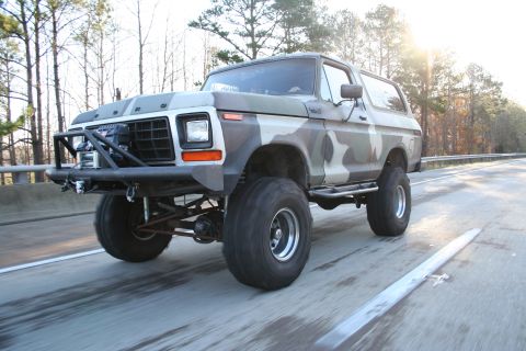
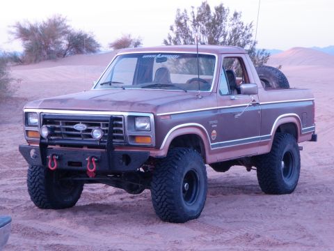
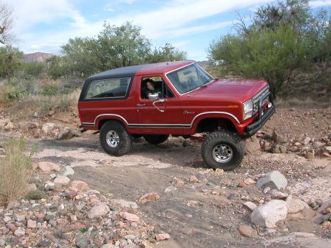
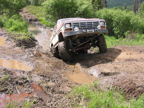
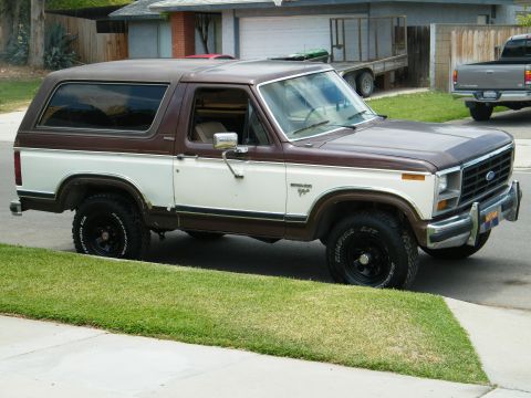
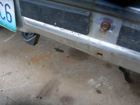
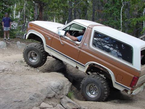
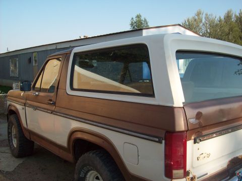
The wall · registered 1980-1986 Broncos
Sorted by depth of documentation. Click any vehicle to open its permanent record.
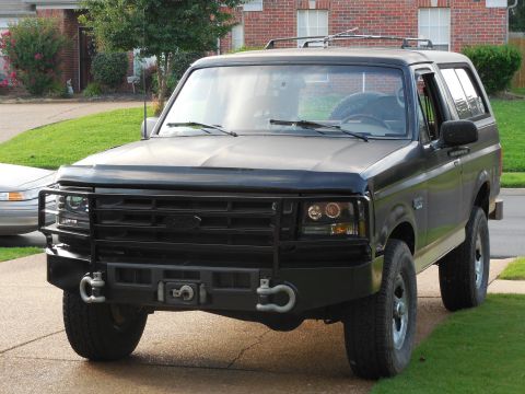
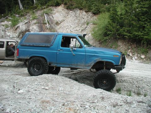
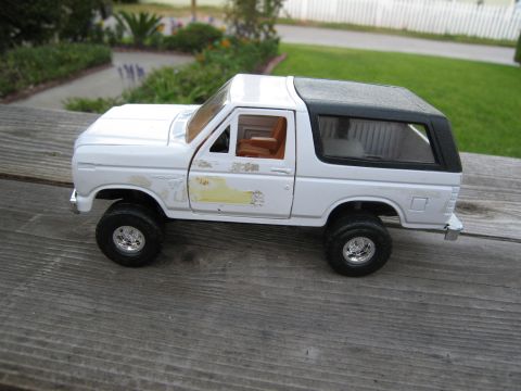
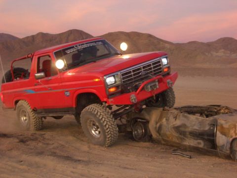
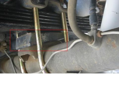
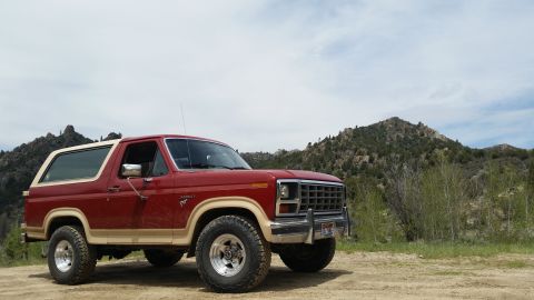
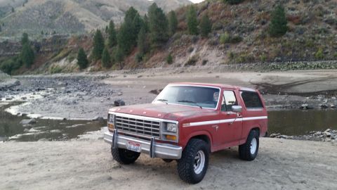
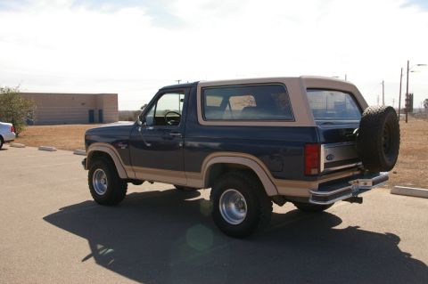
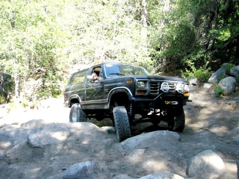
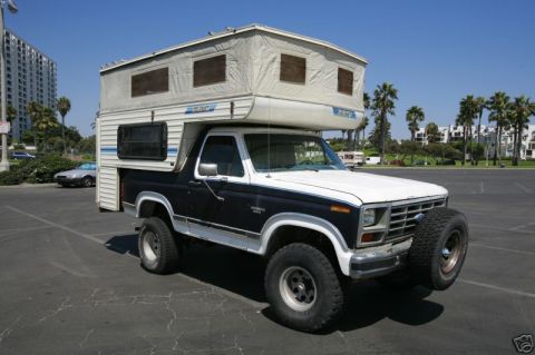
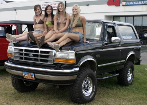
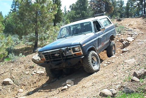
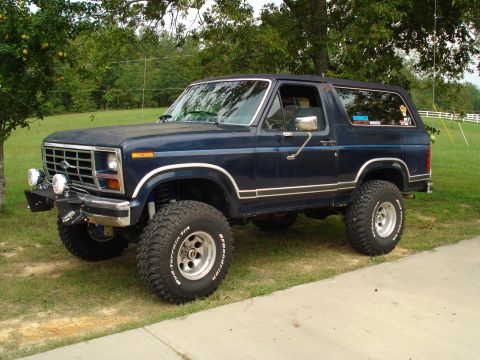
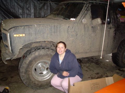
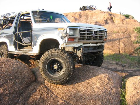
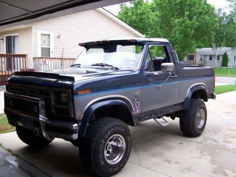
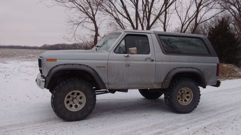
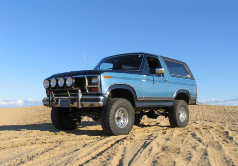
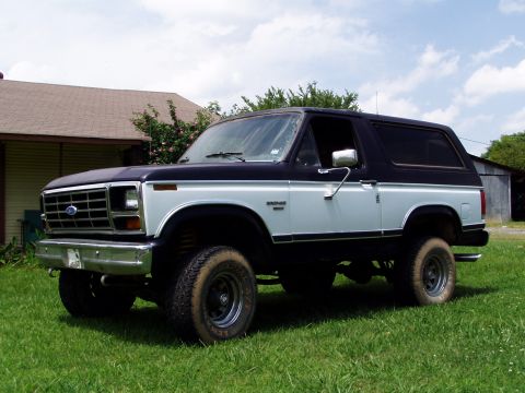
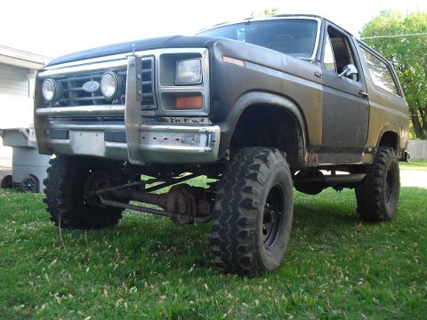
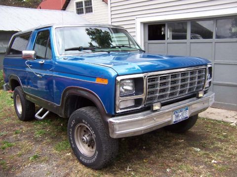
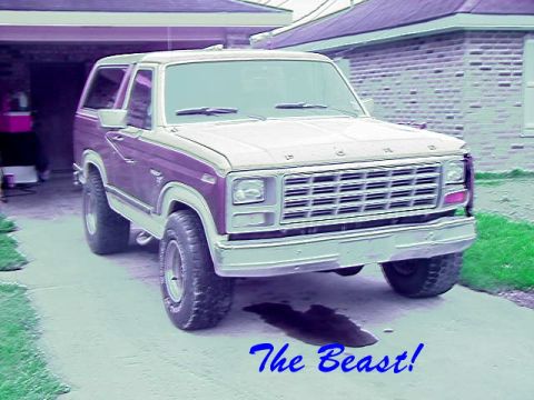
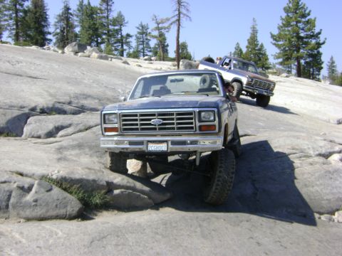
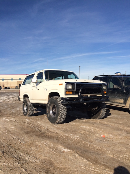

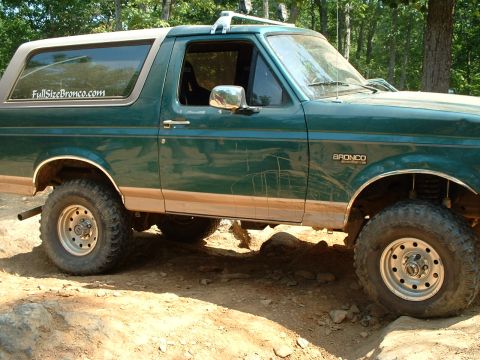
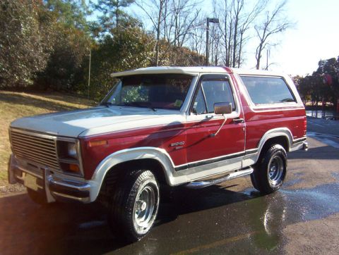
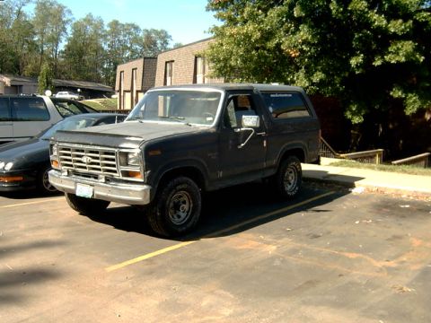
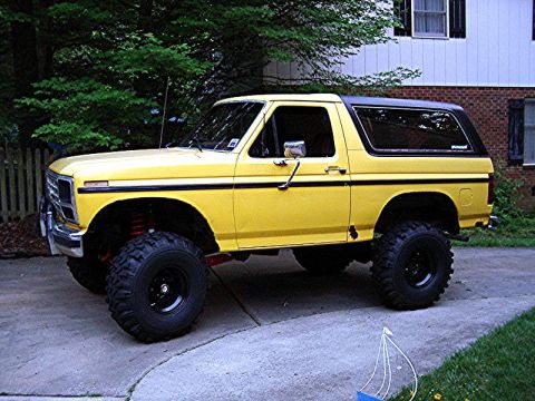
Full year-by-year change log: 1980-1986 Ford Bronco
This log tracks the model-year changes to the third-generation "Bullnose" full-size Ford Bronco (1980-1986) at the level of body, engine, fuel system, drivetrain, suspension, axle, and trim. It is assembled from Ford factory shop manuals and parts catalogs for the 1980-1986 F-series and Bronco, VIN and door data-plate decoding for engine, axle, and trim verification, period road tests and Ford sales literature, and established full-size Bronco reference works and owner registries. Where a date is genuinely uncertain, it is stated as approximate rather than pinned to a specific year.
1980
- Full redesign. The 1980 Ford Bronco opened the third generation with a complete rebody onto Ford's redesigned 1980-1986 F-series chassis, the styling generation enthusiasts call "Bullnose" for its flat, slightly forward-leaning nose and recessed grille.
- Lighter structure for fuel economy. The 1980 redesign cut weight to improve fuel economy in the wake of the 1979 energy crisis, and the early trucks were tuned with that economy priority in mind.
- Twin-Traction Beam front suspension introduced. The 1980 Bronco introduced Ford's Twin-Traction Beam (TTB) independent front suspension, which splits a Dana 44 front axle into two long swinging beams that pivot independently, sprung by coils and located by radius arms.
- Rear axle. The 1980 Bronco used a Ford 9-inch semi-floating live axle on leaf springs at the rear.
- Engines. The 1980 Bronco offered the 300 cubic-inch (4.9L) inline-six as the base engine, plus the 302 (5.0L) V8 returning as the base V8, and the optional 351M (335-series) (5.8L) V8 carried over from the prior generation. The 400 V8 was dropped after 1979.
- Body and wheelbase. The 1980 Bronco remained a two-door full-size SUV with a removable fiberglass rear hardtop over the cargo area, on a 104.7-inch wheelbase.
- Trims. The 1980 Bronco was offered in Custom and XLT trim.
1981
- Carryover refining the redesign. The 1981 Ford Bronco carried over the 1980 redesign, refining the Bullnose body and the Twin-Traction Beam front suspension rather than introducing major mechanical change.
- Continued economy focus. The 1981 Bronco kept the early-1980s emphasis on fuel economy that shaped the launch trucks.
- Drivetrain unchanged. The 1981 Bronco continued with the 300 inline-six, the 302 V8, and the optional 351M (335-series) (5.8L) V8, the TTB front with its Dana 44 axle, the Ford 9-inch semi-floating rear, and four-wheel drive through a transfer case. Some early-1982 trucks were still built from leftover 351M stock.
1982
- Optional 5.8L switches from 351M to 351 Windsor. The 1982 Ford Bronco replaced the carried-over 351M (335-series) (5.8L) V8 with the lighter 351 Windsor (5.8L), which became the top engine option for the rest of the generation. The 335-series 351M was discontinued around 1982, with the Bronco and F-series among its last homes; early-1982 trucks could still appear with leftover 351M stock.
- Front-end styling and grille emblem. The 1982 Bronco shared the revised Ford front-end styling and the Blue Oval grille emblem that arrived on the F-series in this period.
- Chassis unchanged. The 1982 Bronco kept the Twin-Traction Beam front suspension with its Dana 44 axle, the Ford 9-inch semi-floating rear, and four-wheel drive through a transfer case.
1983
- Mid-generation engine availability. The 1983 Ford Bronco carried the 300 inline-six and the 302 and 351 (5.8L) Windsor V8s on the Bullnose body with Twin-Traction Beam front suspension.
- 351 High Output. A 351 High Output (HO) version of the 5.8L Windsor appeared around the mid-1980s; the exact introduction year is not firmly established, so it is noted here as a mid-decade addition rather than pinned to 1983.
- Transmissions. The 1983 Bronco offered manual and automatic transmissions feeding a transfer case for four-wheel drive, with the Dana 44 front axle and Ford 9-inch semi-floating rear unchanged.
1984
- Carryover full-size truck. The 1984 Ford Bronco continued the third-generation full-size truck on the Bullnose body and Twin-Traction Beam front suspension with no major mechanical change.
- Separate compact Bronco II launched. The 1984 model year is when the separate compact Bronco II launched on the Ford Ranger platform with a V6; it is a different, smaller model and not this full-size Bronco.
- Drivetrain unchanged. The 1984 Bronco kept the 300 inline-six and the 302 and 351 V8s, the Dana 44 TTB front, the Ford 9-inch semi-floating rear, and four-wheel drive through a transfer case.
1985
- Eddie Bauer trim introduced. The 1985 Ford Bronco added the Eddie Bauer trim package, bringing two-tone paint and upgraded interior trim above the Custom and XLT levels.
- 5.0L gains throttle-body fuel injection. Around the 1985 model year the 5.0L (302) V8 adopted Ford throttle-body fuel injection (CFI), the same direction the F-series trucks were heading.
- 5.8L stays carbureted. The 1985 Bronco's 5.8L (351 Windsor) V8 remained carbureted while the 5.0L moved to CFI.
- Chassis unchanged. The 1985 Bronco kept the Bullnose body, the Twin-Traction Beam front with its Dana 44 axle, the Ford 9-inch semi-floating rear, and the 300 inline-six as the base engine.
1986
- Final Bullnose year. The 1986 Ford Bronco was the last model year of the third-generation Bullnose body before the 1987 fourth-generation "Bricknose" redesign.
- Fuel system carried over. The 1986 Bronco's 5.0L (302) V8 ran throttle-body fuel injection (CFI), while the 5.8L (351 Windsor) remained carbureted; the 5.8L did not get EFI until the following 1987-1991 trucks.
- Engines and chassis. The 1986 Bronco kept the 300 inline-six as the base engine, offered the 302 and 351 V8s, and retained the Twin-Traction Beam front suspension with its Dana 44 axle and four-wheel drive through a transfer case.
- Rear axle transition begins. The Ford 9-inch semi-floating live axle remained the primary rear axle through most of the 1980-1986 run, but around 1986 Ford began phasing in the smaller, lighter Ford 8.8-inch rear axle across its half-ton trucks; the 8.8-inch then became the standard rear axle for the following 1987 generation.