Ford 5.8L 351 / 6.6L 400 V8 Rocker Arm & Valve Spring In-Chassis Service
Reference · 1980-1986 BroncoAll 40 service procedures
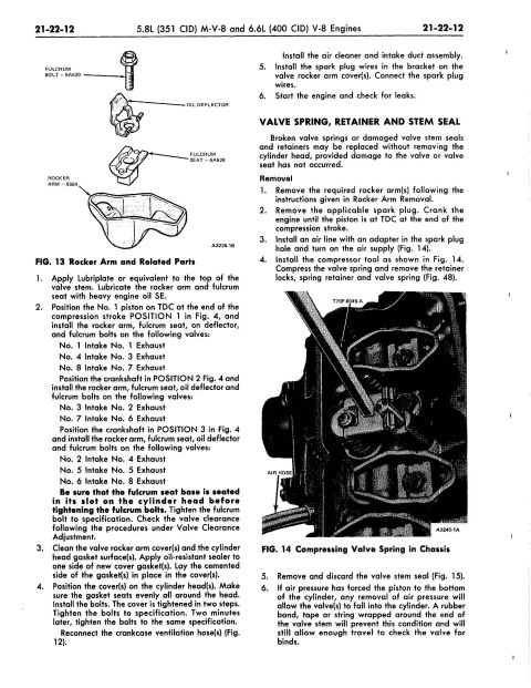
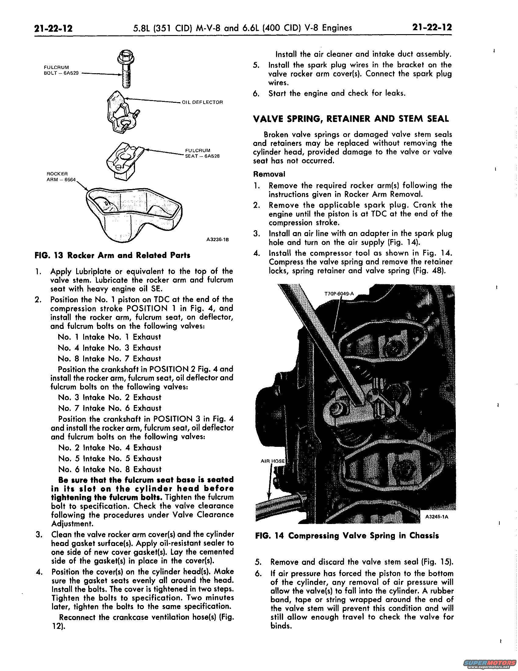
Service manual page for 5.8L and 6.6L V8 engines giving step-by-step rocker arm and valve spring/stem seal removal procedures with figures.
Part of 1980-1986 Ford Bronco Service Procedures
This is page 21-22-12 of a Ford shop manual section covering the 5.8L (351 CID) M-V-8 and 6.6L (400 CID) V-8 engines. The left column continues a rocker arm installation procedure: lubricating the valve stem and rocker arm/fulcrum seat with heavy engine oil SE, positioning the No. 1 piston at TDC on the compression stroke, and installing rocker arms, fulcrum seats, oil deflectors and fulcrum bolts on specific intake/exhaust valves at three crankshaft positions (Positions 1, 2 and 3 per Fig. 4). It stresses seating the fulcrum seat base in its cylinder head slot before tightening, then covers valve clearance checking, rocker cover gasket installation with oil-resistant sealer, two-step cover bolt tightening, reconnecting crankcase ventilation hoses, air cleaner installation, spark plug wire routing, and leak checking. Figure 13 illustrates the rocker arm and related parts with part numbers: Fulcrum Bolt 6A529, Fulcrum Seat 6A528, Rocker Arm 6564. The right column begins the Valve Spring, Retainer and Stem Seal removal procedure, done in-chassis using compressed air through the spark plug hole and compressor tool T70P-6049-A (shown in Fig. 14), with a caution about using a rubber band or tape on the valve stem to prevent a valve dropping into the cylinder if air pressure is lost.
Is this accurate? Sign in to help verify it.
Frequently asked questions
- What is the rocker arm installation sequence for the Ford 351M/400 V8?
- With the No. 1 piston at TDC end of compression stroke (Position 1), install rockers on No. 1, 4, 8 intake and No. 1, 3, 7 exhaust; at Position 2, on No. 3, 7 intake and No. 2, 6 exhaust; at Position 3, on No. 2, 5, 6 intake and No. 4, 5, 8 exhaust.
- What must be checked before tightening the fulcrum bolts?
- Be sure the fulcrum seat base is seated in its slot on the cylinder head before tightening the fulcrum bolts, then tighten to specification and check valve clearance per the Valve Clearance Adjustment procedure.
- Can valve springs and stem seals be replaced without removing the cylinder head?
- Yes. Broken valve springs or damaged valve stem seals and retainers may be replaced in-chassis, provided the valve or valve seat is not damaged, by holding the valve up with compressed air through the spark plug hole and using compressor tool T70P-6049-A.
- How do you keep the valve from dropping into the cylinder if air pressure is lost?
- Wrap a rubber band, tape or string around the end of the valve stem; this prevents the valve from falling into the cylinder while still allowing enough travel to check the valve for binds.
- What part numbers are shown in the rocker arm diagram (Fig. 13)?
- Fulcrum Bolt: 6A529, Fulcrum Seat, 6A528, and Rocker Arm, 6564, along with the oil deflector.
No comments yet.