Subaru WRX H4DOTC ECU Pin Voltage Table - Engine Speed/Tach Output B136 Pin 22
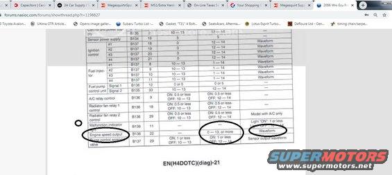
Forum screenshot of a service-manual ECM input/output signal table showing per-circuit voltages and waveform notes.
Part of 2012-2016 Subaru Impreza Manual Pages
This is a screenshot of a NASIOC forum post displaying a scanned Subaru factory service manual page (footer code EN(H4DOTC)(diag)-21) containing an ECU connector pin voltage reference table. The table lists ECU signals by name, connector number (B134, B135, B136, B137), pin number, expected voltage with ignition on, expected voltage with the engine running, and notes (such as whether a waveform should be observed). Covered signals include control unit power supply, sensor power supply, ignition control outputs #1-#4, fuel injectors #1-#4, fuel pump control unit signals 1 and 2, A/C relay control, radiator fan relay 1 and 2 control, malfunction indicator light, engine speed output, and purge control solenoid valve. Hand-drawn circles highlight the Engine speed output row (connector B136, pin 22, running voltage 0-13 or more, waveform note), consistent with the uploader researching a tachometer/RPM output signal. The browser tab title indicates the thread concerns a 2006 WRX ECU pinout, and the H4DOTC code indicates a turbocharged flat-four engine. Readers can use this page to identify the ECU pin carrying the engine speed (tach) signal and to verify correct voltages on ignition, injector, fan, A/C, and purge solenoid circuits.
Is this accurate? Sign in to help verify it.
Frequently asked questions
- Which ECU pin carries the engine speed (tach) output on this Subaru ECU?
- Per the table, Engine speed output is on connector B136, pin 22, showing 0-13 volts or more with the engine running, with a waveform note.
- What connector and pins are the ignition control outputs on?
- Ignition control #1-#4 are on connector B137, pins 18, 19, 20, and 21. They read 0 V with ignition on and 12-14 V with the engine running (waveform).
- Which pins are the fuel injector signals?
- Fuel injectors #1-#4 are on connector B137, pins 8, 9, 10, and 11, reading 10-13 V ignition-on and 1-14 V running.
- What voltage should the radiator fan relay control pins show?
- Radiator fan relay 1 (B136 pin 18) and relay 2 (B136 pin 29) read ON: 0.5 V or less and OFF: 10-13 V with ignition on, or OFF: 12-14 V running. Relay 2 applies to models with A/C only.
- What page of the service manual is this table from?
- The page footer reads EN(H4DOTC)(diag)-21.
Comments
More from this build


No comments yet.