This document details engine assembly procedures, including measurements for crankshaft and connecting rod components.
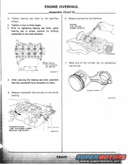
ENGINE OVERHAUL Assembly (Contd) 5. Tighten bearing cap bolts to the specified torque. Tighten in two or three stages. Prior to tightening bearing cap bolts, place bearing cap in proper position by shifting cnnksha in the axial direction. i9 / = a . QWQEQDES KO L/KV / E (ici43gz@;@ [email protected].@" , . [/79 . g r: V E? I, {q as . 52 N-m (4.7 . 53 kg-m, . ,/ ,3. / Cid - 33 mm 147 2 - e; L: SEMOJ A After securing the bearing an bolts, ascertain than the cmnkshaflturns smoothly by hand. 5. Measure crankshaft free and play at the center bearing. UniK: mm (in) 0J5 - 0.21 10.0024 - 0.0087) Crunluhlk and may: } W-v limit: 0.50 (0.0197) SEMDI7A 6. Measure connecting rod clearance. End ploy: 0.10 ~ 0.37 nun (0.0mm - 0.0146 in! 7. Make sure of the cylinder No. on connecting rod and cap. Cyiindev number SEM723A
Comments
More from this build


No comments yet.