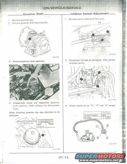
This document page details the governor shaft and inhibitor switch adjustment procedures with accompanying diagrams.
Men Governor Shaft ' 1. Remove governor cap. 2. Remove governor shaft securing bolt. SAY373 4. Disassemble, check and reassemble governor shaft assembly. Refer toRepair for Component Parts. When installing governor cap, pay attention to its direction. : Governor cap 5AT203A Inhibitor Switch Adjustment 1. Remove control cable end from unit. 5117375 2. Disconnect harness at connector. then remove inhibitor switch. SATI97A 0 Check continuity at N", "P" and R ranges. n a . N and P ranges 0.0 R range 0- 5Arism AT1O
Comments
More from this build


No comments yet.