Backup / Reverse Light Wiring Diagram - With & Without Relay (Toggle Switch)
Reference · 1997-2006 WranglerAll 10 wiring diagrams
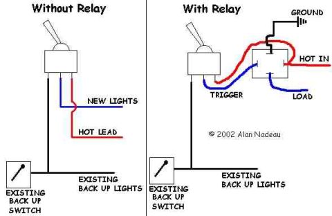
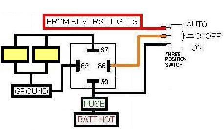
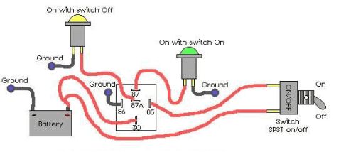
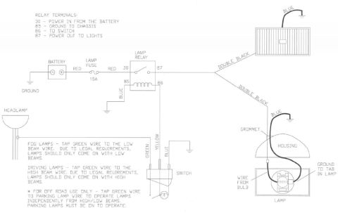

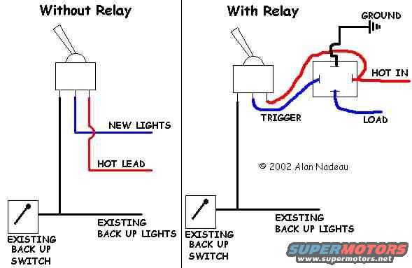
Compares adding lights to existing backup lights with no relay (simple tap of hot lead) versus using a relay where the backup switch triggers the relay that feeds the new load.
Part of 1997-2006 Jeep Wrangler Wiring Diagrams
This document is a simplified wiring diagram illustrating two methods of adding auxiliary backup (reverse) lights to a vehicle. The left side, labeled "Without Relay," shows a toggle switch wired so that a hot lead (red) and a wire to the new lights (blue) pass directly through the switch, which taps into the circuit fed by the existing backup switch that powers the existing backup lights. The right side, labeled "With Relay," shows the preferred relay-based method: a toggle switch provides a trigger signal (blue) to a relay, the relay receives a heavy-gauge hot input (red, "HOT IN") and ground (black, "GROUND"), and the switched output goes to the auxiliary lights via the "LOAD" wire (blue). Both versions connect to the existing backup switch and existing backup lights circuit. Wire colors in the drawing distinguish hot/power feeds (red), switched/load and trigger wires (blue), and ground (black). The diagram is credited "© 2002 Alan Nadeau." No fuse ratings, wire gauges, part numbers, or relay pin numbers are given; it is a conceptual schematic showing how a relay isolates the high-current lighting load from the toggle switch and factory backup light circuit.
Is this accurate? Sign in to help verify it.
Frequently asked questions
- What two wiring methods does this diagram show for adding backup lights?
- It shows wiring new backup lights through a toggle switch directly ("Without Relay") and wiring them through a relay triggered by the toggle switch ("With Relay").
- What connections does the relay need in the "With Relay" version?
- The relay has four connections shown: GROUND (black), HOT IN (red power feed), TRIGGER (blue wire from the toggle switch), and LOAD (blue wire to the lights).
- How is the toggle switch wired in the "Without Relay" version?
- A red HOT LEAD and a blue wire labeled NEW LIGHTS run through the toggle switch, which also ties into the circuit from the existing backup switch and existing backup lights.
- Does the diagram use the factory backup light circuit?
- Yes, both versions show connections to the EXISTING BACK UP SWITCH and EXISTING BACK UP LIGHTS.
- Who created this diagram and when?
- The diagram is marked "© 2002 Alan Nadeau."


No comments yet.