Home/
Registry/
Ford/
Fairlane/
1966-1967/
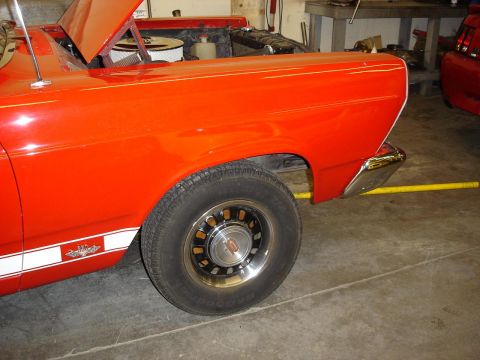
1966 Ford Fairlane/
Photo
supermotors.net/registry/media/304436
1965 Mustang 130 Amp 3G Alternator Conversion Wiring Diagram & Install Guide

Reference · 1966-1967 FairlaneAll 1 wiring diagrams
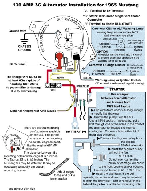
Color-coded wiring diagram for installing a 130-amp 3G alternator on a 1965 Mustang with terminal and fuse callouts.
Part of 1966-1967 Ford Fairlane Wiring Diagrams
This document is an illustrated installation guide/wiring diagram for upgrading a 1965 Ford Mustang to a 130 amp Ford 3G alternator, in this example using a Motorola-brand alternator and harness sourced from a 1993 Ford Taurus. It shows the 3G alternator's terminal connections: the "A" terminal to the B+ terminal, the "S" stator terminal to a single-wire stator connector, and the "I" terminal to a source that is hot in RUN/START. Wiring callouts include wire colors Blk/Wht, Yel/Wht, and Lt Grn/Red, a chassis ground, a 175A MEGA fuse in the charge circuit, connections through the starter solenoid to the battery positive terminal, and an optional aftermarket amp gauge. Two excitation circuit options are diagrammed: cars with a GEN/ALT warning lamp (with an optional 560 ohm resistor in parallel in case the lamp burns out) and cars with a 5-gauge cluster (using a 560 ohm resistor). The guide warns the charge wire must be at least 6 gauge to handle 130+ amps. Mechanical notes cover pulley swapping (use a 15/16 socket, install the original 65A alternator's V-groove pulley without the fan, torque 60-100 ft-lbs), mounting-hole spacing differences (original 7", Taurus 3G 8-1/2"), extending the lower bracket by 3 inches, and shimming to cure belt squeal. Ends with "use at your own risk."
Is this accurate? Sign in to help verify it.
Frequently asked questions
- How do I wire a 3G alternator into a 1965 Mustang?
- Connect the "A" terminal to the B+ terminal, the "S" stator terminal to the single-wire stator connector, and the "I" terminal to a wire that is hot in RUN/START (the "I" terminal wire from the old regulator setup, going to the warning lamp or ignition switch). Run the charge wire through a 175A MEGA fuse to the starter solenoid and battery positive, and ground the alternator to the chassis.
- What size charge wire is needed for a 130 amp 3G alternator?
- The charge wire must be at least 6 gauge, capable of handling 130+ amps, to prevent fire or damage due to overheating.
- What fuse is used in this 3G alternator conversion?
- A 175A MEGA fuse is placed in the charge wire between the alternator B+ output and the starter solenoid/battery.
- How is the "I" terminal wired on cars with a 5-gauge cluster (no warning lamp)?
- The alternator "I" terminal is connected through a 560 ohm resistor to the ignition switch, on a circuit that is hot when the key is in RUN/START.
- What torque should the 3G alternator pulley nut be tightened to?
- 60 - 100 ft. lbs. Do not over-tighten the pulley or damage will occur to the front bearing and/or housing.
- Will the Taurus 3G alternator bolt right into the original brackets?
- Not exactly, the original alternator's mounting holes are 7 inches apart while the Taurus 3G's are 8-1/2 inches, so it may be necessary to modify the bottom mounting bracket and add 3 inches to the end of the lower bracket.
No comments yet.