Home/
Registry/
Mercury/
Cougar/
1967-1970/
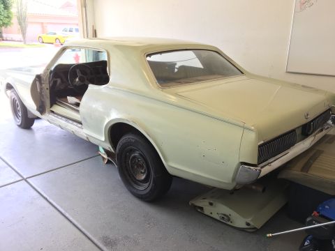
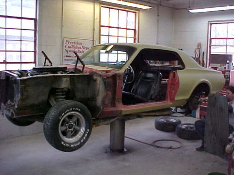
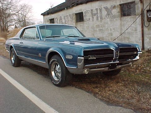
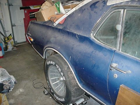
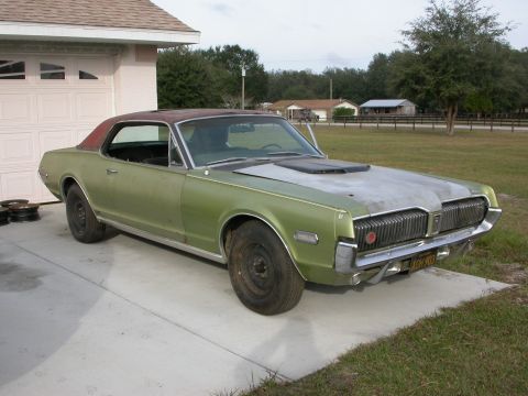
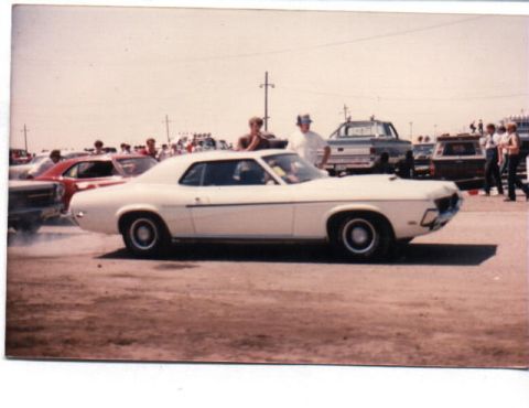
1968 Mercury Cougar/
Photo
supermotors.net/registry/media/516409
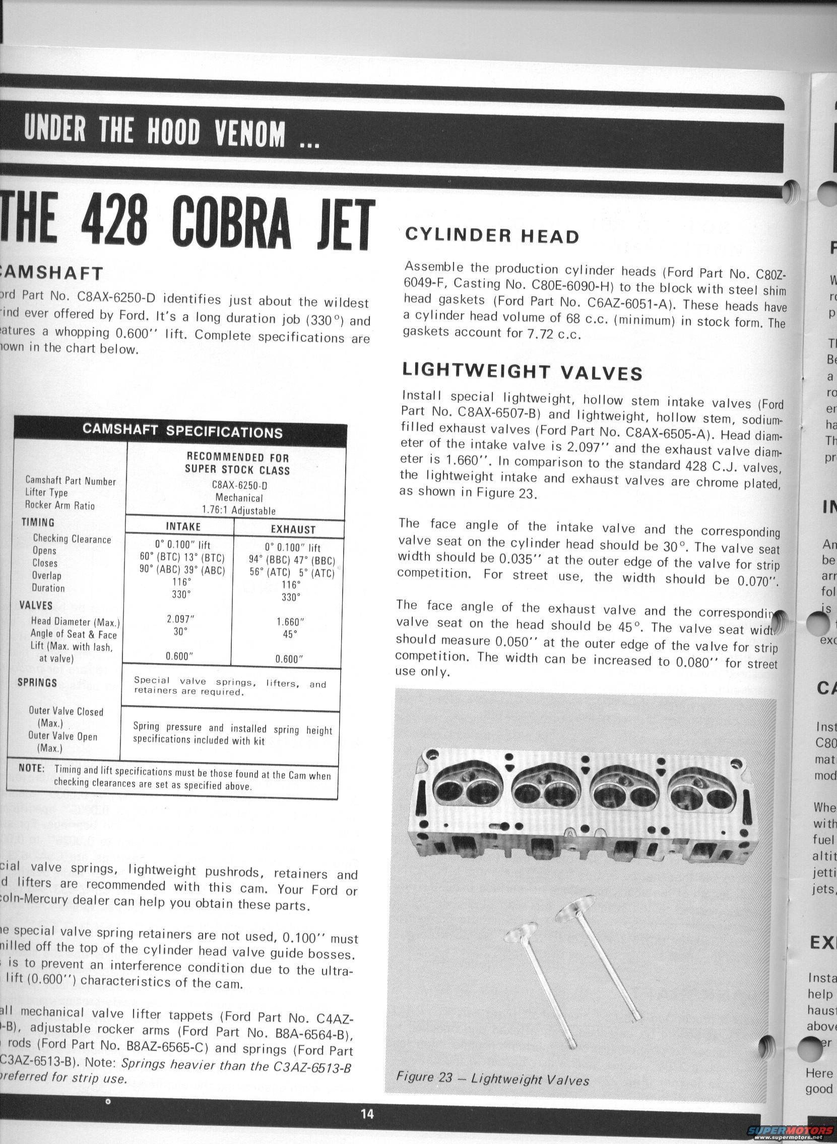
Page 14 of a 428 Cobra Jet performance manual with camshaft spec…
Reference · 1967-1970 CougarAll 10 manual pages


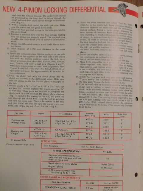
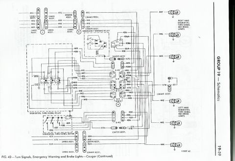
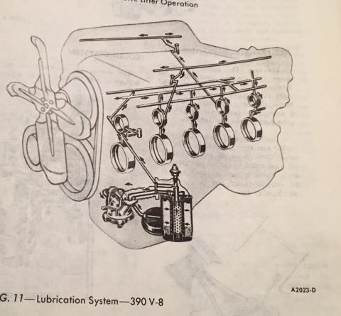
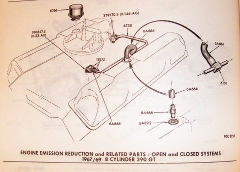
Page 14, Under the Hood Venom: the 428 Cobra Jet, with C8AX-6250-D camshaft specs (330 degree duration, 0.600" lift), cylinder heads and lightweight valves.
Part of 1967-1970 Mercury Cougar Manual Pages
UNDER THE H000 VENOM Na lHE 423 COBRA JET :AMSHAFT 3rd Part No. C8AX-6250-D identifies just about the wildest 'ind ever offered by Ford. It's a long duration job (330) and iatures a whopping 0.600 lift. Complete specifications are town in the chart below. CAMSHAFT SPECIFICATIONS RECOMMENDED FDR SUPER STOCK CLASS Cainshalt Part Number CBAXVGZEOVD Lifter Type Mechanical RockerArin Ratio i.7:l Adjustable TIMING INTAKE EXHAUST Checking Clearance 0 u 100" lift 0 0 iUU im UFens 60 (BTCJ l3" (BTU) 94 (BBCl 47 (BBC) 5'05 90 (ABC) 39 (ABC) 55 (ATCi 5 (ATCl Overlap HE 115': Duration 330 330 VALVES H U Head Diameter (Mam 230:7 1:50 Angle 0! Seat & Face Lift (Max. Willi lash, ,, H at valve) 0600 0.600 Special valve springs, lifters, and SPRINGS retainers are required Enter Valve Closed (Maxi Spring pressure and installed spring height Outer Valve Open specifications included with kit (Maxi NOTE: Timing and lift specifications must be these fuund at the Cain when checking clearances are set as specified almve. Cial valve springs, lightweight pushrods, retainers and d lifters are recommended with this cam. Your Ford or :oIn-Mercury dealer can help you obtain these parts. ie special valve spring retainers are not used, 0100" must nilled off the top of the cylinder head valve guide bosses. , is to prevent an interference cond lift (0600) Characteristics of the cam. ition due to the ultra all mechanical valve lifter tappets (Ford Part No. C4AZ- l-Bl, adjustable rocker arms (Ford Part No. BBA-6564-B), i rods (Ford Part No BBAZ-6565-C) and springs (Ford Part C3AZ~6513~BL Note: Springs heavier than the C3AZ6573-B are/erred for strip use. F Assemble the production cylinder heads (Ford Part No. CBOZ- w 6049-F, Casting No. C80E-6090H) to the block with steel shim n head gaskets (Ford Part No. CBAZ-GOBi-A). These heads have p a cylinder head volume of 68 cc (minimum) in stock form. The gaskets account for 7.72 C.C. l TI Bt LIGHTWEIGHT VALVES v f o lnstall special lightweight, hollow stem intake valves (Ford er Part No. C8AX-6507B) and lightweight, hollow stem, sodium ha filled exhaust valves (Ford Part No. C8AX-6505-Alt Head diam- Th eter of the intake valve is 2.097" and the exhaust valve diam- pri eter is 1.660". In comparison to the standard 428 C.J. valves, the lightweight intake and exhaust valves are Chrome plated, as shown in Figure 23. V The face angle of the intake valve and the corresponding , valve seat on the cylinder head should be 30. The valve seat 1 An width should be 0.035" at the outer edge of the valve for strip i be competition. For street use, the width should be 0.070. ( Edi l The face angle of the exhaust valve and the correspondinm1 51 valve seat on the head should be 45". The valve seat wid ' should measure 0.050 at the outer edge of the valve for strip : competition. The width can be increased to 0.080" use only, eX( for street iCI lnst J C80 mat mod Whe with fuel altit jetti jets, EXl lnsta help , hausi l abov: Here Figure 23 Lightweight Valves good
Is this accurate? Sign in to help verify it.
No comments yet.