Home/
Registry/
Mercury/
Cougar/
1967-1970/
1968 Mercury Cougar/
Photo
supermotors.net/registry/media/848341
Shelby American Blueprint S8MS 9C507A - Bearing Housing, Lucas Mark II Fuel Inj
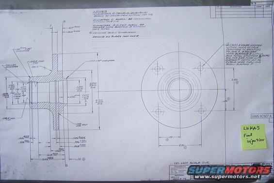
Engineering blueprint of a Lucas fuel-injection flange with bolt-hole pattern, dimensions, notes and a Shelby Automotive title block.
This is a scanned Shelby American, Inc. engineering blueprint (drawing number S8MS 9C507 A) for a machined aluminum part titled 'Bearing Housing, Timing Gear, Fuel Inj,' for the 'Lukas (Lucas) Mark II Fuel Injection' model application. The drawing, drafted by D.D. Pushak on 5-12-67 with engineer J. Dunn and approvals dated through 5-17-67, shows a cross-section view and a face view of a flanged cylindrical bearing housing. Key dimensions include a 4.500/4.510 flange diameter, 2.500/2.510 pilot diameter, 1.618/1.622 bore (Dia A), and four 17/64 (.265) mounting holes on a 2.50 x 2.50 square pattern with 21/32 (.656) spotfaces. Notes call out concentricity requirements (Dia C within .001 TIR, Dia D within .004 TIR), squareness of diameters A, C, D & E to surface B within .002 total, and deburring to max .005 R. Material is specified as aluminum 6062 T6, drawn at 2x full size with standard Shelby tolerances (decimals ±.01/±.005, fractions ±1/16, angles ±15'). A yellow sticky note identifies it as 'LUKAS Fuel injection.' The document is useful to anyone researching or reproducing Shelby's 1967 Lucas mechanical fuel injection experimental hardware.
Is this accurate? Sign in to help verify it.
Frequently asked questions
- What part does Shelby drawing S8MS 9C507 A show?
- A bearing housing for the timing gear of the fuel injection system, listed for the 'Lukas (Lucas) Mark II Fuel Inj' model, made of aluminum 6062 T6.
- When was this Shelby American blueprint drawn?
- It was drafted by D.D. Pushak on 5-12-67, with designer, engineer (J. Dunn), and approval dates of 5-16-67 and 5-17-67.
- What are the mounting hole specs on the flange?
- Four 17/64 (.265) holes located within .005 R of true position relative to Dia A, square with surface B within .005 total, spotfaced 21/32 (.656) dia on the far side flush with surface F, not extending more than .010 below surface F. The holes sit on a 2.50 x 2.50 pattern.
- What concentricity tolerances does the drawing require?
- Diameters C (bearing housing) must be concentric within .001 TIR, diameters D within .004 TIR, and diameters A, C, D & E must be square with surface B within .002 total.
- What scale and tolerances apply to this drawing?
- Scale is 2x full size, 'Do Not Scale Dwg.' Unless otherwise noted: decimals .00 ±.01 and .000 ±.005, fractions ±1/16, angles ±15 minutes.
Comments
More from this build

No comments yet.