Home/
Registry/
Mercury/
Cougar/
1989-1997/
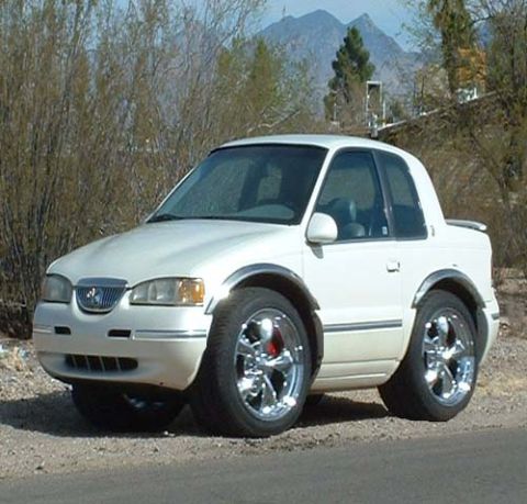
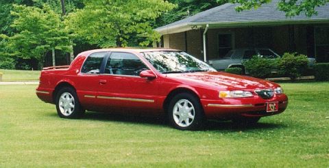
1997 Mercury Cougar/
Photo
supermotors.net/registry/media/626322
Ford Transmission Shift Solenoid SS1/SS2 Connector Pinout Diagram D14116-B

Ford transmission diagnostic diagram: vehicle harness connector test pins (1, 27, 91/97) for SS1, SS2, VPWR plus the internal solenoid harness wire-color pinout.
Part of 1989-1997 Mercury Cougar Wiring Diagrams
This wiring diagram (drawing number D14116-B) illustrates the shift solenoid (SS1 and SS2) circuits at the transmission connectors. The upper illustration shows the transmission vehicle harness connector face, mapping EEC/PCM test pins to solenoid circuits: test pins 91 and 97 carry SS1 and SS2 VPWR (solenoid power), test pin 27 is SS1, and test pin 1 (labeled P/O) is SS2, each with a leader line pointing to the corresponding cavity on the connector drawing. The lower illustration shows the transmission internal harness: a round connector face with SS1, SS VPWR, and SS2 pin locations identified, plus the internal wiring pigtail. Wire colors are labeled along the pigtail: white/black stripe, white, and black, terminating at a small solenoid connector whose terminals are identified as SS2, SS1, and SS VPWR. The diagram lets a technician identify which test pins and wire colors correspond to shift solenoids 1 and 2 and their power feed when diagnosing shift solenoid electrical problems at either the external vehicle harness connector or the transmission's internal harness. No vehicle year, model, or transmission model is stated on the document itself.
Is this accurate? Sign in to help verify it.
Frequently asked questions
- Which test pins correspond to the shift solenoids at the transmission vehicle harness connector?
- Test pins 91 and 97 are SS1 and SS2 VPWR (power), test pin 27 is SS1, and test pin 1 (P/O) is SS2.
- What wire colors are used in the transmission internal harness for the shift solenoid circuits?
- The internal harness wires are labeled white/black stripe, white, and black, running to a connector with terminals identified as SS2, SS1, and SS VPWR.
- What circuits are shown on this diagram?
- It shows the SS1 and SS2 shift solenoid signal circuits and their shared solenoid power (SS VPWR / SS1 AND SS2 VPWR) at both the transmission vehicle harness connector and the transmission internal harness.
- What is the drawing/reference number of this diagram?
- The diagram is identified as D14116-B.
Comments
More from this build
No comments yet.